Waveguides
A waveguide is a special form of
transmission line consisting of a hollow, metal tube. The
tube wall provides distributed inductance, while the empty
space between the tube walls provide distributed
capacitance:
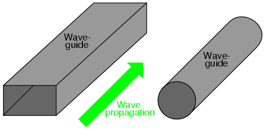
Waveguides are practical only for signals of
extremely high frequency, where the wavelength approaches
the cross-sectional dimensions of the waveguide. Below such
frequencies, waveguides are useless as electrical
transmission lines.
When functioning as transmission lines,
though, waveguides are considerably simpler than
two-conductor cables -- especially coaxial cables -- in
their manufacture and maintenance. With only a single
conductor (the waveguide's "shell"), there are no concerns
with proper conductor-to-conductor spacing, or of the
consistency of the dielectric material, since the only
dielectric in a waveguide is air. Moisture is not as severe
a problem in waveguides as it is within coaxial cables,
either, and so waveguides are often spared the necessity of
gas "filling."
Waveguides may be thought of as conduits for
electromagnetic energy, the waveguide itself acting as
nothing more than a "director" of the energy rather than as
a signal conductor in the normal sense of the word. In a
sense, all transmission lines function as conduits of
electromagnetic energy when transporting pulses or
high-frequency waves, directing the waves as the banks of a
river direct a tidal wave. However, because waveguides are
single-conductor elements, the propagation of electrical
energy down a waveguide is of a very different nature than
the propagation of electrical energy down a two-conductor
transmission line.
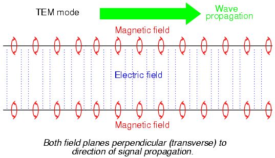
All electromagnetic waves consist of
electric and magnetic fields propagating in the same
direction of travel, but perpendicular to each other. Along
the length of a normal transmission line, both electric and
magnetic fields are perpendicular (transverse) to the
direction of wave travel. This is known as the principal
mode, or TEM (Transverse Electric
and Magnetic) mode. This mode of wave propagation can
exist only where there are two conductors, and it is the
dominant mode of wave propagation where the cross-sectional
dimensions of the transmission line are small compared to
the wavelength of the signal.
At microwave signal frequencies
(between 100 MHz and 300 GHz), two-conductor transmission
lines of any substantial length operating in standard TEM
mode become impractical. Lines small enough in
cross-sectional dimension to maintain TEM mode signal
propagation for microwave signals tend to have low voltage
ratings, and suffer from large, parasitic power losses due
to conductor "skin" and dielectric effects. Fortunately,
though, at these short wavelengths there exist other modes
of propagation that are not as "lossy," if a conductive tube
is used rather than two parallel conductors. It is at these
high frequencies that waveguides become practical.
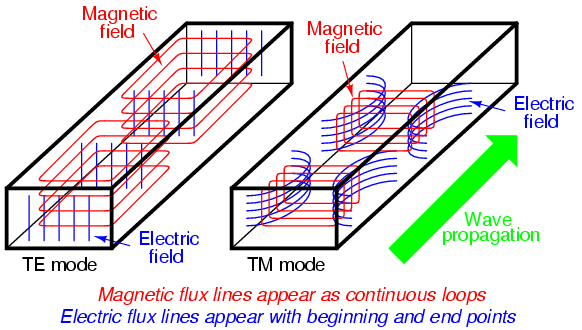
When an electromagnetic wave propagates down
a hollow tube, only one of the fields -- either electric or
magnetic -- will actually be transverse to the wave's
direction of travel. The other field will "loop"
longitudinally to the direction of travel, but still be
perpendicular to the other field. Whichever field remains
transverse to the direction of travel determines whether the
wave propagates in TE mode (Transverse Electric)
or TM (Transverse Magnetic) mode.
Many variations of each mode exist for a
given waveguide, and a full discussion of this is subject
well beyond the scope of this book.
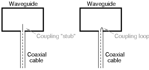
Signals are typically introduced to and
extracted from waveguides by means of small antenna-like
coupling devices inserted into the waveguide. Sometimes
these coupling elements take the form of a dipole, which is
nothing more than two open-ended stub wires of appropriate
length. Other times, the coupler is a single stub (a
half-dipole, similar in principle to a "whip" antenna, 1/4λ
in physical length), or a short loop of wire terminated on
the inside surface of the waveguide:
In some cases, such as a class of vacuum
tube devices called inductive output tubes (the
so-called klystron tube falls into this category), a
"cavity" formed of conductive material may intercept
electromagnetic energy from a modulated beam of electrons,
having no contact with the beam itself:
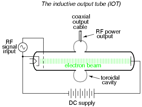
Just as transmission lines are able to
function as resonant elements in a circuit, especially when
terminated by a short-circuit or an open-circuit, a
dead-ended waveguide may also resonate at particular
frequencies. When used as such, the device is called a
cavity resonator. Inductive output tubes use toroid-shaped
cavity resonators to maximize the power transfer efficiency
between the electron beam and the output cable.
A cavity's resonant frequency may be altered
by changing its physical dimensions. To this end, cavities
with movable plates, screws, and other mechanical elements
for tuning are manufactured to provide coarse resonant
frequency adjustment.
If a resonant cavity is made open on one
end, it functions as a unidirectional antenna. The following
photograph shows a home-made waveguide formed from a tin
can, used as an antenna for a 2.4 GHz signal in an "802.11b"
computer communication network. The coupling element is a
quarter-wave stub: nothing more than a piece of solid copper
wire about 1-1/4 inches in length extending from the center
of a coaxial cable connector penetrating the side of the
can:
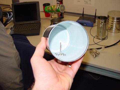
A few more tin-can antennae may be seen in
the background, one of them a "Pringles" potato chip can.
Although this can is of cardboard (paper) construction, its
metallic inner lining provides the necessary conductivity to
function as a waveguide. Some of the cans in the background
still have their plastic lids in place. The plastic, being
nonconductive, does not interfere with the RF signal, but
functions as a physical barrier to prevent rain, snow, dust,
and other physical contaminants from entering the waveguide.
"Real" waveguide antennae use similar barriers to physically
enclose the tube, yet allow electromagnetic energy to pass
unimpeded.
-
REVIEW:
-
Waveguides are metal tubes
functioning as "conduits" for carrying electromagnetic
waves. They are practical only for signals of extremely
high frequency, where the signal wavelength approaches the
cross-sectional dimensions of the waveguide.
-
Wave propagation through a waveguide may
be classified into two broad categories: TE
(Transverse Electric), or TM (Transverse Magnetic),
depending on which field (electric or magnetic) is
perpendicular (transverse) to the direction of wave
travel. Wave travel along a standard, two-conductor
transmission line is of the TEM (Transverse
Electric and Magnetic) mode, where both fields are
oriented perpendicular to the direction of travel. TEM
mode is only possible with two conductors and cannot exist
in a waveguide.
-
A dead-ended waveguide serving as a
resonant element in a microwave circuit is called a
cavity resonator.
-
A cavity resonator with an open end
functions as a unidirectional antenna, sending or
receiving RF energy to/from the direction of the open end.
|
