|
The new data-logger software is not yet
completely finished.
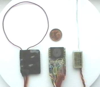
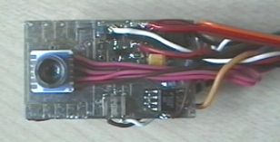
But the hardware design is frozen and
will probably not be changed anymore.
The printed circuit board is a bit
smaller than the old one (36x22mm).
But unfortunately the new one can
measure analog input signals only with 10 bit
resolution.
The sensor for barometric altitude and
its amplifier are contained on the printed circuit board
now.
Since the dissolution of altitude (10
bit) is too rough for the climb rate, an additional
circuit is on the board.
An amplifier for current measurements as
well as an amplifier for measuring bridges are likewise
contained on the board.
Thus only an additional shunt or a
measuring bridge (e.g. a differential pressure sensor
with pitot tube) needs to be attached.
The measured data can be stored in a
EEPROM and / or transferred by telemetry or by cable to
a PalmPilot or PC.
The baud rate for the telemetry mode is
selectable. 1200 and 9600 baud are available.
The data rate for the transfere of the
the stored data to the Palm / PC was increased to 38400
baud.
Version V2.5 are different to version
V2.4 in case of the circuit for current measurement.
Therefore BEC-systems can used now.
Version V2.9 supports also GPS-receiver
with ANTARIS chipset and simultaneously using of
internal temperature sensor of MS5534A and external
DS1820 sensor. This version can use 24C256, 24C512 or
24C1024 EEPROMs and has an internal 'bootloader'
implemented.
With V2.9g you can configure the
datalogger for the 'Multilogging mode' (more than one
loggs possible after switch off).
V2.9h supports DS18S20 temperature
sensors, 2-wire connection for the temp sensor (connect
pin1 and 3 of the sensor) and better start condition for
GPS using.
Click Here to View Circuit
Click Here to View Circuit
Click Here to View Circuit
Following a modified circuit for the
current measurement:
Instead of the analog pressure sensor
MPX4100 you can now connect a combined pressure and
temperature sensor MS5534A.
The connectors which are normaly used by
the additional LTC2400 and the connector for the analog
variometer signal are used then.
The benefit of this sensor is the larger
range (300...1100mbar) and the calibration.
Attention: To use this sensor the
reference voltage must adjust to 3.3 ... 3.6V (R1, R2).
Besides the sensor must be registered to
the logger (use the "Loggerleserprogram" for this
reason).
This decoder is necessary if the
bi-phase-code (Manchester-2-code) is used by the
telemetry. This feature is configurable by the "Logerleserprogram".
The decoder is installed after the
telemetry receiver and transform the Man-2-code to the
normally used RS232-code for the PC or Palm.
The adjustable resistor adjust the
threshold for the used data.The led show if the treshold
is exeeded.
If RSSI is not available on the receiver
then pin6 of the PIC12F629 must be connected to pin1.
Layout for Telemetry-Decoder
The software is in the development phase
and can measure only the following signals at the
moment.
5 analog channels (4x 10 bit, 1x 8 bit)
1 period duration input, for number of
revolutions, speed etc. (16bit, pin 21)
1 frequency input for speed etc. (16bit,
pin 6)
1 temperature input (8Bit, DS1820,
Pin11)
3 RC channel inputs (additional 1 RC
channel for switching the logger ON and OFF, RC0)
In place of the RC channels, the digital
outputs of a ADXL202 (acceleration-sensor) can be used.
GPS (longitude, latitude and altitude),
38400 baud NMEA interface used
Simple vario tone output (pin 13)
Additionally it's possible to use a 24
bit analog digital converter (LTC-2400) for more
accuracy.
Telemetry data can be transmitted by
using Manchester-2-code or RS232 format.
Version V2.9 has an internal 'Bootloader'
for easier software updates via the RS232-connection
(without PIC-burner). (For upgrades connect pin 5 and
pin1 of the EEPROM with a 220ohm-resistor and switch the
logger on).
Automatically recognize of the used
EEPROM 24C256 / 24C512 / 24C1024.
With version V2.9g you can use the
datalogger for more than one flight also after switch of
the power of the datalogger.
|
