|
I usually use one motor for the left
wheel and one for the right wheel. The problem is that
the motors are never perfectly matched and my RCX ends
up going in circles. I thought of buying two rotation
sensors to keep track of the rotation of both wheel
axles. However this would use up two sensor ports,
leaving only one for my other sensors. Also it would
cost a few extra dollars, which is against my philosophy
of hobbies: never spend a dollar if you can instead have
lots of fun making something with extra functionality
out of parts I already have in the RCX box and my
basement tool-room. If it takes weeks or months of
planning, researching, building and programming, so much
the better. The use of crazy glue, hot-glue (multi-coloured
if possible) and heat-shrink tubing is a definite plus.
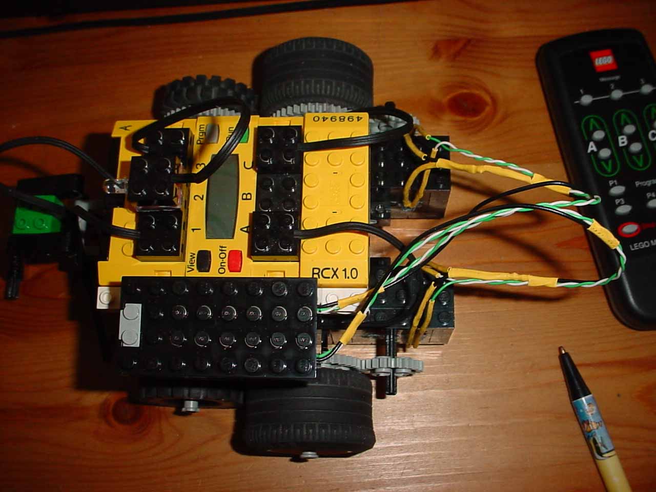
This website will document how I built my
one-sensor-port, double-rotation sensor out of parts I
had in the house. I just installed it on my RCX and the
robot does indeed go in a fairly straight line (much,
much better than the large circle it went in without
it.).
I became interested in building a
rotation sensor from the book: "Extreme Mindstorms" and
the website of Michael Gasperi, one of the authors. This
link to his website is for a torque sensor but it gave
me ideas for the sensor electronics I used. On page 277
of the book, he documents an opto-interrupter made with
Lego beams, regular parts, a 6 hole pulley wheel and an
axle. I wanted to have two of these, one for each drive
wheel and I wanted them to share one sensor port because
I'm already running out of sensor ports. So I set about
figuring out the electronics and software to make the
idea work. I used LegOS, by the way, because it's fast
and flexible.
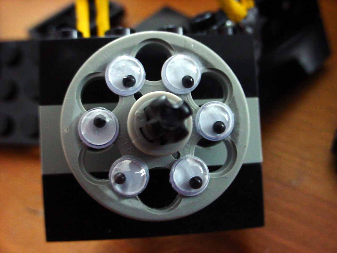
I started out with Michael Gasperi's
idea with the 6 whole pulley installed in a Lego
enclosure with axle and beams so it could move. I used
phototransistors and infrared LED's because I thought
they would use less power than visible light LED's and
CdS photo resistors. I built the Lego box with the beams
but found the space between the pulley holes was less
than the diameter of the pulley holes. I thought that a
better waveform would ensue if I decreased the area of
the holes. So I stuck little plastic "googly-eyes" (the
kind you see on pet rocks) that were exactly the
diameter of the pulley holes in between the holes (six
in all). I also used a smooth technic half bush on the
axle to keep the pulley wheel in place. Then I enlarged
the beam holes to allow the photodiodes and IR LED's to
fit, using a hand held drill (1/4"). Drill only as much
as needed, you want a little flange to help seat the
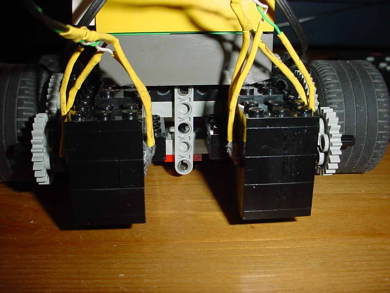
LED's and phototransistors.

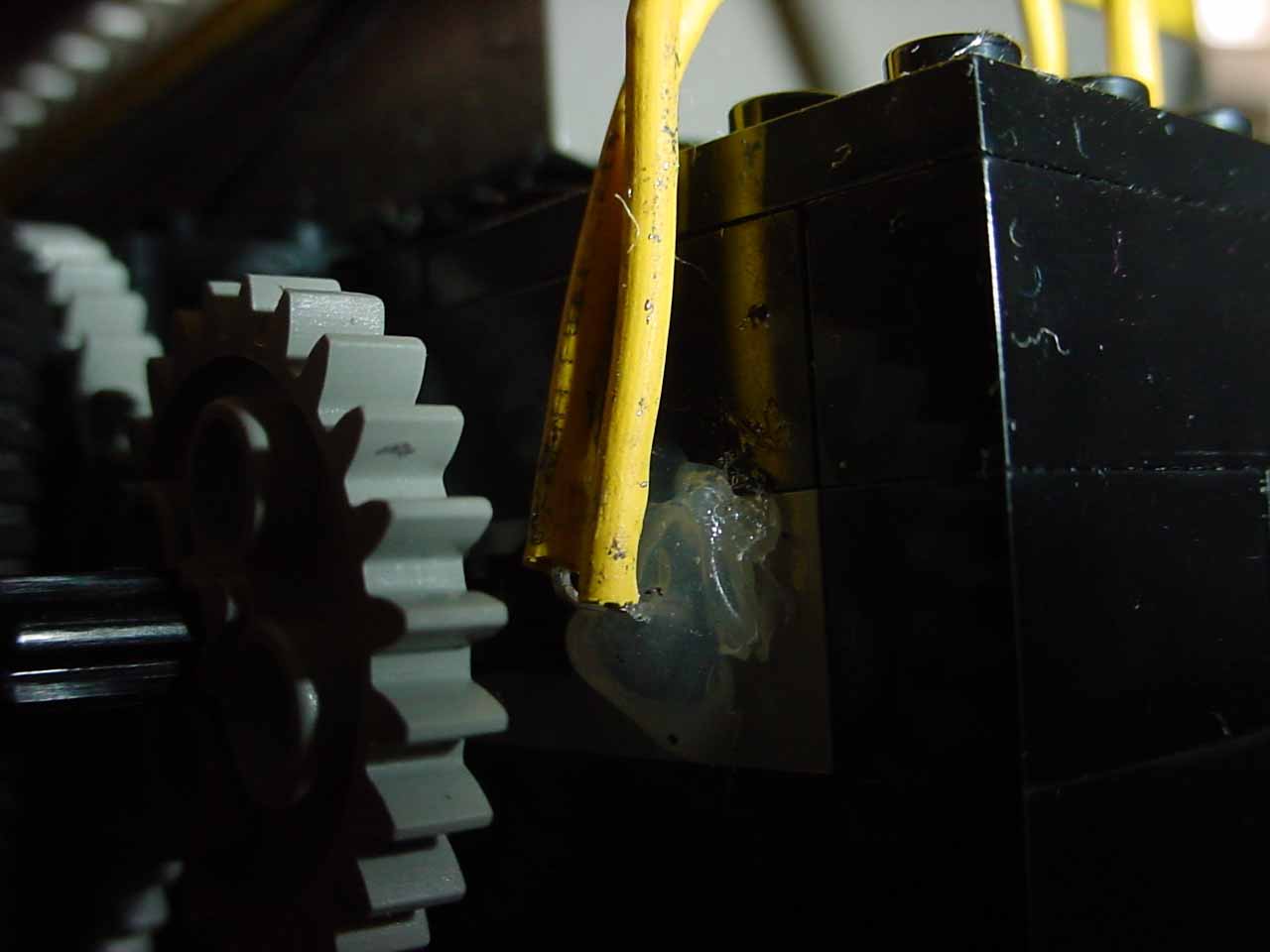
You'll have to hot-glue them in. Figure
out which side you'll want them when you're finished; I
made my two sensor modules mirror images. I used silver
coloured hot glue (which I bought at a craft store) to
keep the light from getting in and interfering with the
sensor readings.
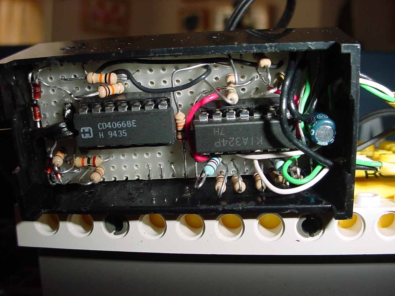
Next I developed the electronics. The
sensor power supply I took from the torque sensor along
with the idea to use a LM324 and 4066. Here's the
schematic and here's a picture. I drew it using Eagle
which you can download for free. The circuit sort of
evolved. I found the second op-amp used as a Schmidt
trigger really made the output sharper. The 4066 seems
to make the RCX raw reading independent of the battery
power. Remember on the schematic I only showed one
channel. You'll need two for right and left. I also
didn't show the power connections for the IC's. Don't
forget to ground the two unused control leads on the
4066. The pinout links should help you. My IR LED's were
not equal so the current-limiting resistor for one was
5.5K and for the other 9.1K. I adjusted this resistor
(R8) using an oscilloscope and a trim pot to make the
output a perfect square wave while the axle was spun by
a RCX motor running at full power, ~330 RPM.
At this point, I found that the right
and left sensor modules would keep up when spinning ~
330 RPM and there was no "crossover" interference
between the right and left channels. Then I cut the
largest bit of perf-board that would fit in a Lego (Znap)
9V battery holder that I had removed the battery
connections from to make more room. It wasn't too hard
to fit all the components on. It helped to use a Dremel
to remove bumps from inside the battery box. It was a
bit tricky to get all the wires connected as I didn't
plan carefully enough. However in the end it all fit, if
snugly.
Of course, the LegOS driver for the
sensor needed to be programmed as the electronics were
being tested. First I made a small program to read the
raw values for the four states. In the driver; Off was
FF80, right C0C0, left AB80 and both on 8CC0. I used
RAW>>13 to make the readings in the range 0-7. So "off"
became 7, right 6, left 5 and both on 4. You'll have to
make a little program to check your own raw readings and
enter the numbers in the program. Note the numbers I use
make the programming easier (see the driver).
I did a lot of experimentation, checking
the values the RCX received from the sensor in real
time. Eventually I came up with the final "driver" which
seems pretty good to me. I've tried to document the
driver so it makes sense. I noticed a fair number of
anomalous values just after the RUN button is pressed.
After a delay the sensor was pretty good with only a few
out of many thousand readings being in between the
numbers noted above. Once I introduced a one second
delay before the main programme started to run the RCX
ran in a fairly good straight line. |
