|
This Mark3 version of the Infra Red
extender is a special version designed to control
appliances that use high frequency modulated IR remote
controls.
Click here to view Circuit
IR appliances use pulses (control
signals) sent over a modulated IR carrier wave. The
carrier wave may be modulated at various frequencies,
36-38KHz being the most popular.Some Satellite receivers
use even higher frequencies than this. The IR1 remote
module receives an infra red signal and separates
control pulses from the modulation. To re-transmit, a
555 timer is configured as an astable oscillator. The
555 timer is controlled by the signal on the reset pin,
high generating a carrier and low no carrier. Each
control pulse turns on the oscillator for the duration
of a logic high signal and off for a logic 0 signal,
thereby creating a newly modulated IR signal. The IR
module, part number IR1 is available from Harrison
Electronics in the UK, IR1 may not be listed in their
catalogue but if you ask for an IR1, they will send you
the correct part. The IR1 arrives in a small aluminium
case, the connections viewed from underneath are shown
below:
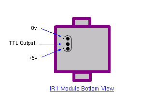
Infra Red Module, IR1 Pinout
Harrison Electronics have limited
supplies of the IR1 but as a replcement a standard IR
module like the TSOP1838 may be used. The pinout is
shown below:
The carrier frequency is determined by
R1 and C3, values shown work at 39.7 kHz, but these may
be altered to provide different carrier frequencies. The
final CMOS 4049 invertor ensures that under "no signal"
conditions both LED's are also off.
C1 100u 10V
C2 100n polyester
C3 120p silver mica
C4 100n polyester
R1 150k
R2 2k2k
R3 1k
R4 47R 1W
Q1 BC109C
IC1 LM7805
IC2 555
IC3 IR1 module from Harrison Electronics or TSOP1838
IC4 4049 CMOS Invertor LED1 Red LED (or any visible
colour)
LED2 TIL38 or part YH70M from Maplin Electronics
Pinouts for the IC's can be found on my IC pinout page.
First the component side of the board is
shown below.
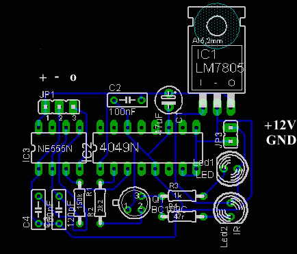
And now the pcb itself.
The Mark 3 circuit is an improvement
over the Mark 1 and 2 circuits, however the drive from
Q1 inverts the polarity of the output pulse. In some
cases this can cause problems so the output stage is
rewired as an emitter follower. |
