Let's begin with a semiconductor gate circuit in
need of simplification. The "A," "B," and "C" input signals are assumed to
be provided from switches, sensors, or perhaps other gate circuits. Where
these signals originate is of no concern in the task of gate reduction.
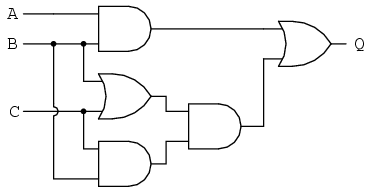
Our first step in simplification must be to write a Boolean expression
for this circuit. This task is easily performed step by step if we start by
writing sub-expressions at the output of each gate, corresponding to the
respective input signals for each gate. Remember that OR gates are
equivalent to Boolean addition, while AND gates are equivalent to Boolean
multiplication. For example, I'll write sub-expressions at the outputs of
the first three gates:
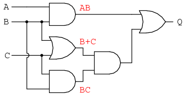
. . . then another sub-expression for the next gate:
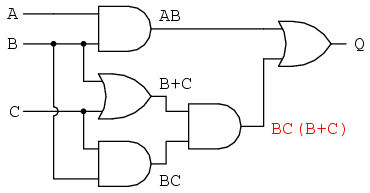
Finally, the output ("Q") is seen to be equal to the expression AB + BC(B
+ C):
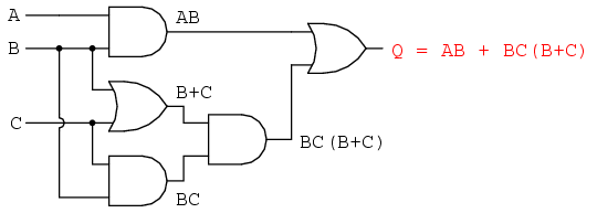
Now that we have a Boolean expression to work with, we need to apply the
rules of Boolean algebra to reduce the expression to its simplest form
(simplest defined as requiring the fewest gates to implement):
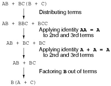
The final expression, B(A + C), is much simpler than the original, yet
performs the same function. If you would like to verify this, you may
generate a truth table for both expressions and determine Q's status (the
circuits' output) for all eight logic-state combinations of A, B, and C, for
both circuits. The two truth tables should be identical.
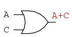
Now, we must generate a schematic diagram from this Boolean expression.
To do this, evaluate the expression, following proper mathematical order of
operations (multiplication before addition, operations inside parentheses
before anything else), and draw gates for each step. Remember again that OR
gates are equivalent to Boolean addition, while AND gates are equivalent to
Boolean multiplication. In this case, we would begin with the sub-expression
"A + C", which is an OR gate:
The next step in evaluating the expression "B(A + C)" is to multiply (AND
gate) the signal B by the output of the previous gate (A + C):
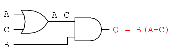
Obviously, this circuit is much simpler than the original, having only
two logic gates instead of five. Such component reduction results in higher
operating speed (less delay time from input signal transition to output
signal transition), less power consumption, less cost, and greater
reliability.
Electromechanical relay circuits, typically being slower, consuming more
electrical power to operate, costing more, and having a shorter average life
than their semiconductor counterparts, benefit dramatically from Boolean
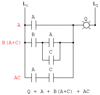
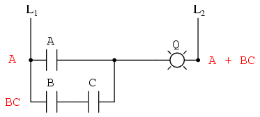
simplification. Let's consider an example circuit:
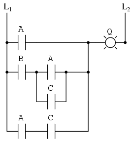
As before, our first step in reducing this circuit to its simplest form
must be to develop a Boolean expression from the schematic. The easiest way
I've found to do this is to follow the same steps I'd normally follow to
reduce a series-parallel resistor network to a single, total resistance. For
example, examine the following resistor network with its resistors arranged
in the same connection pattern as the relay contacts in the former circuit,
and corresponding total resistance formula:
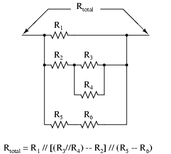
Remember that parallel contacts are equivalent to Boolean addition, while
series contacts are equivalent to Boolean multiplication. Write a Boolean
expression for this relay contact circuit, following the same order of
precedence that you would follow in reducing a series-parallel resistor
network to a total resistance. It may be helpful to write a Boolean
sub-expression to the left of each ladder "rung," to help organize your
expression-writing:
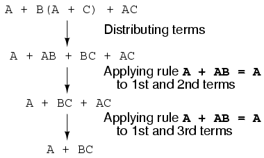
Now that we have a Boolean expression to work with, we need to apply the
rules of Boolean algebra to reduce the expression to its simplest form
(simplest defined as requiring the fewest relay contacts to implement):
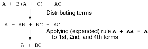
The more mathematically inclined should be able to see that the two steps
employing the rule "A + AB = A" may be combined into a single step, the rule
being expandable to: "A + AB + AC + AD + . . . = A"
As you can see, the reduced circuit is much simpler than the original,
yet performs the same logical function:
REVIEW: To convert a gate circuit to a Boolean expression, label each gate
output with a Boolean sub-expression corresponding to the gates' input
signals, until a final expression is reached at the last gate. To convert a Boolean expression to a gate circuit, evaluate the
expression using standard order of operations: multiplication before
addition, and operations within parentheses before anything else. To convert a ladder logic circuit to a Boolean expression, label each
rung with a Boolean sub-expression corresponding to the contacts' input
signals, until a final expression is reached at the last coil or light. To
determine proper order of evaluation, treat the contacts as though they
were resistors, and as if you were determining total resistance of the
series-parallel network formed by them. In other words, look for contacts
that are either directly in series or directly in parallel
with each other first, then "collapse" them into equivalent Boolean
sub-expressions before proceeding to other contacts. To convert a Boolean expression to a ladder logic circuit, evaluate
the expression using standard order of operations: multiplication before
addition, and operations within parentheses before anything else. |
