Voltage comparator
PARTS AND MATERIALS
-
Operational amplifier, model 1458 or 353
recommended (Radio Shack catalog # 276-038 and 900-6298,
respectively)
-
Three 6 volt batteries
-
Two 10 kΩ potentiometers, linear taper
(Radio Shack catalog # 271-1715)
-
One light-emitting diode (Radio Shack
catalog # 276-026 or equivalent)
-
One 330 Ω resistor
-
One 470 Ω resistor
This experiment only requires a single
operational amplifier. The model 1458 and 353 are both
"dual" op-amp units, with two complete amplifier circuits
housed in the same 8-pin DIP package. I recommend that you
purchase and use "dual" op-amps over "single" op-amps even
if a project only requires one, because they are more
versatile (the same op-amp unit can function in projects
requiring only one amplifier as well as in projects
requiring two). In the interest of purchasing and stocking
the least number of components for your home laboratory,
this makes sense.
CROSS-REFERENCES
Lessons In Electric Circuits, Volume
3, chapter 8: "Operational Amplifiers"
LEARNING OBJECTIVES
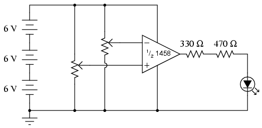
SCHEMATIC DIAGRAM
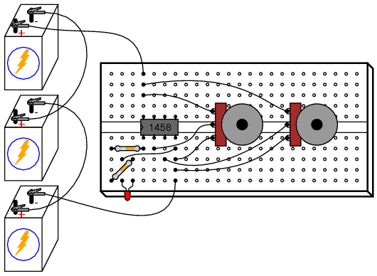
ILLUSTRATION
INSTRUCTIONS
A comparator circuit compares two
voltage signals and determines which one is greater. The
result of this comparison is indicated by the output
voltage: if the op-amp's output is saturated in the positive
direction, the noninverting input (+) is a greater, or more
positive, voltage than the inverting input (-), all voltages
measured with respect to ground. If the op-amp's voltage is
near the negative supply voltage (in this case, 0 volts, or
ground potential), it means the inverting input (-) has a
greater voltage applied to it than the noninverting input
(+).
This behavior is much easier understood by
experimenting with a comparator circuit than it is by
reading someone's verbal description of it. In this
experiment, two potentiometers supply variable voltages to
be compared by the op-amp. The output status of the op-amp
is indicated visually by the LED. By adjusting the two
potentiometers and observing the LED, one can easily
comprehend the function of a comparator circuit.
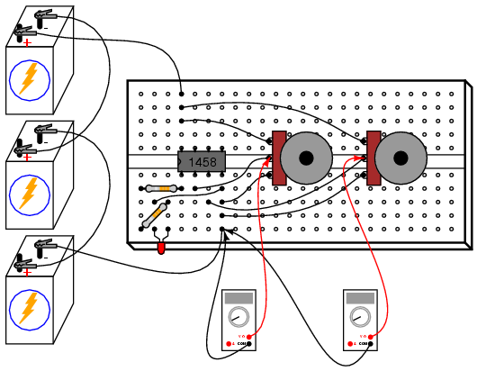
For greater insight into this circuit's
operation, you might want to connect a pair of voltmeters to
the op-amp input terminals (both voltmeters referenced to
ground) so that both input voltages may be numerically
compared with each other, these meter indications compared
to the LED status:
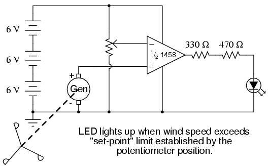
Comparator circuits are widely used to
compare physical measurements, provided those physical
variables can be translated into voltage signals. For
instance, if a small generator were attached to an
anemometer wheel to produce a voltage proportional to wind
speed, that wind speed signal could be compared with a
"set-point" voltage and compared by an op-amp to drive a
high wind speed alarm:
 |
