Microcontroller Advanced
Kit - Digital Clock Using Four 7-Segment Displays
We can use a 2051
microcontroller to build a clock using 7 segment
displays. This is tricky since we need to seperately
control 28 LEDs and have 2 input switches and we
only have 15 I/O lines.
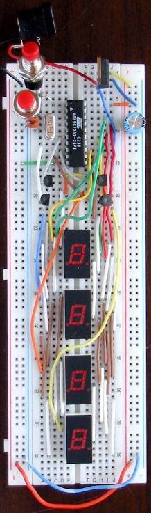
Start by building the circuit as shown in the
7
segment display tutorial except you
can leave off the 5 volt connection to pin 3 of the
7 segment display. Then repeat this 3 times for the
next three 7 segment displays. As you can see in the
picture you can just run jumper wires from one
display to the next.
At this point you can test your connections by
connecting each display pin 3 to 12 volts using a
240 ohm resistor. Then use the program in the
7
segment display tutorial and each display should
light up with the same thing as in the other
tutorial.
Now comes the trick to putting a different number
on each display. The basic idea is to only turn one
display on at a time. So we write the number to all
the displays, turn on one display, then turn off
that display and go to the number for the next
display. We turn the displays on and off using NPN
transistors. Each display has a transistor that
provides power. The transistor is turned on and off
by an output pin from the 2051. This way we can use
4 outputs to turn on the 4 displays one at a time.
This lets us control 28 LEDs with only 11 outputs.
To add in the transistors, connect the collector
of each transistor to the 12VDC power supply. Then
connect the emitter of one transistor to pin 3 of
the top display. Connect the base of this transistor
to P3.2 (Pin 6) of the 2051. Connect the next
transistor's emitter to pin 3 of the next display
and the base to P3.3 (Pin 7). Connect the next
transistor's emitter to pin 3 of the next display
and the base to P3.4 (Pin 8). Connect the final
transistor's emitter to pin 3 of the bottom display
and the base to P3.5 (Pin 9).
Finally, add in the switches by connecting them
both to ground. Then connect one to P3.0 (Pin 2) and
the other to P3.1 (Pin 3). P3.0 will be our "Set"
input and P3.1 will change the value while setting.