|
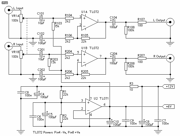
Prompted by a reader's question, this is
a useful addition to a car audio system, especially if
one wants to use a crossover circuit and other low level
amplifiers. The circuit contains two audio preamps, with
a maximum gain of 21dB (this can be reduced, as it may
be too high for many applications).
Also provided is an "artificial earth"
("ground" for US readers), which can be used to supply a
centre voltage for crossovers and other additions - such
as a parametric equaliser, or even a simple graphic
equaliser.
The input impedance is a minimum of 15k
(it will be much more than this for most control
settings), and output impedance is 100 Ohms - low enough
to drive any line level input.
The preamp circuit is completely
conventional, and by necessity is AC coupled throughout.
The artificial earth is derived by two resistors (R1 and
R2), which will set the "earth" at exactly 1/2 the
supply voltage. This is nominally 13.8V in all cars,
since this is the proper charging voltage for a 12V
battery.
To reduce the maximum gain, simply
reduce the values of R105 and R205. For example,
reducing these to 4k7 will provide a maximum gain of 3
(10dB), which in reality is probably enough.

Figure 1 - The Circuit For The Preamp
There is quite a lot of filtering,
because the vehicle supply is notoriously noisy. In some
instances it might be necessary to replace R9 with a
suitable noise filter module, or an inductor.
The artificial earth is obtained from
the "6V" terminal, and is used in place of the real
earth connection for the additional circuitry. It may
(will) be necessary in some cases to either ...
-
Add input and output capacitors to the
added circuitry
-
Reverse the polarity of existing
polarised input / output capacitors. The +ve lead of all
electrolytics must be connected to the circuit, with the
-ve lead as the input, output or chassis earth as
appropriate.
In addition, electrolytic capacitors in
feedback circuits that are connected to earth should be
connected to the actual earth, not the artificial earth,
or performance may suffer.
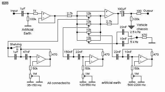
As an example, I have included the
circuit for my parametric equaliser and sub-woofer
equaliser (Project 28), with the required modifications
shown. The same principle applies to crossover networks
or any other signal processing circuit.

Figure 2 - Modified Version Of Project
28
As can be seen, all the original earth
connections except the one new one (the "Vehicle
Chassis" connection) go to the artificial earth. If this
is not done, the circuit simply will not work, as it
will be trying to function with the input at the same
potential as the negative supply terminal on the opamp.
One word of warning - if the device you
are connecting to the artificial earth is expected to
have significant AC or DC earth currents (> 10mA), this
system will not work. It is designed for low current
(preamp) type applications only. A higher powered
version could be developed from the basics presented
here, but as long as speaker type currents are kept
away, this design should be quite acceptable.
By the way, the above circuit would be
an ideal addition to almost any car sub-woofer
installation, leaving out the upper midrange and treble
controls (they are not useful for a sub). Alternatively,
you could have two of the 35-150Hz controls, which will
give much better control of the lower bass region. The
120-550Hz control is likely to be useful to eliminate
unwanted peaks (or dips) over the crossover region. You
may want to lower the frequency, by increasing the value
of one or both capacitors for this control. Doubling the
value of either cap will halve the frequency (i.e. from
60 to 225Hz).
|