|
There are many articles about the Baycom
software and many quite different diagrams on the net.
Here is another but this time you can also download the
complete Baycom v1.7 software as well as a PCB foil
pattern and component layout. It's all here on Harry's
Homebrew Homepages. First of all, here is the circuit
diagram:
There is nothing particularly dificult
and construction is quite straight forward. I have made
up this PCB so as not to use any PCB wire links at all.
Be sure to use the correct 9-pin 'D' type connector so
the pins fit in the board. The two outer holes for
mounting the 9-pin 'D' type connector should be 3mm Dia.
and the holes for the pins are 1.2mm Dia. The PCB is
also tailored for a PCB mounting 5-pin DIN socket. These
holes should also be 1.2mm Dia. All other holes on the
PCB are 0.9mm Dia. The 22K resistor close to the 5-pin
DIN socket is only fitted when your transciever PTT
switch is by means of a DC short on the MIC lead (most
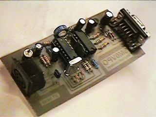
hand-held radio's). Here is my finished modem.
To align the modem, using an
oscilloscope, connect it to the receiver and open the
squelch on an unused channel and watch the waveform on
pin 6 of the 74HC04. Adjust the 47K pot so that the
noise is centered on the screen and not all at the top
or bottom of the screen - i.e. the noise should be just
as much positive 5v as it is 0v. If you do not have an
oscilloscope then adjust the 47K for a DC voltage of
2.5v on pin 6 of the 74HC04.
Full instructions for setting up the
software are given in the software ZIP package. The PCB
foil, component overlay and Baycom software are given in
the DOWNLOAD section of my homepages. If you want a PCB
ready made then just look at my KITS page. I hope to
have a ready made PCB available soon. The TCM3105 is
supposed to be obsolete but you can still buy it from N
R Bardwell, see my Component suppliers page.
|
