With BogusBus, our signals were very simple and
straightforward: each signal wire (1 through 5) carried a single bit of
digital data, 0 Volts representing "off" and 24 Volts DC representing "on."
Because all the bits arrived at their destination simultaneously, we would
call BogusBus a parallel network technology. If we were to improve
the performance of BogusBus by adding binary encoding (to the transmitter
end) and decoding (to the receiver end), so that more steps of resolution
were available with fewer wires, it would still be a parallel network. If,
however, we were to add a parallel-to-serial converter at the transmitter
end and a serial-to-parallel converter at the receiver end, we would have
something quite different.
It is primarily with the use of serial technology that we are forced to
invent clever ways to transmit data bits. Because serial data requires us to
send all data bits through the same wiring channel from transmitter to
receiver, it necessitates a potentially high frequency signal on the network
wiring. Consider the following illustration: a modified BogusBus system is
communicating digital data in parallel, binary-encoded form. Instead of 5
discrete bits like the original BogusBus, we're sending 8 bits from
transmitter to receiver. The A/D converter on the transmitter side generates
a new output every second. That makes for 8 bits per second of data being
sent to the receiver. For the sake of illustration, let's say that the
transmitter is bouncing between an output of 10101010 and 10101011 every
update (once per second):
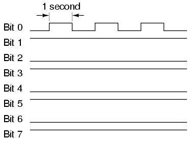
Since only the least significant bit (Bit 1) is changing, the frequency
on that wire (to ground) is only 1/2 Hertz. In fact, no matter what numbers
are being generated by the A/D converter between updates, the frequency on
any wire in this modified BogusBus network cannot exceed 1/2 Hertz, because
that's how fast the A/D updates its digital output. 1/2 Hertz is pretty
slow, and should present no problems for our network wiring.
On the other hand, if we used an 8-bit serial network, all data bits must
appear on the single channel in sequence. And these bits must be output by
the transmitter within the 1-second window of time between A/D converter
updates. Therefore, the alternating digital output of 10101010 and 10101011
(once per second) would look something like this:
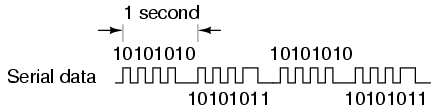
The frequency of our BogusBus signal is now approximately 4 Hertz instead
of 1/2 Hertz, an eightfold increase! While 4 Hertz is still fairly slow, and
does not constitute an engineering problem, you should be able to appreciate
what might happen if we were transmitting 32 or 64 bits of data per update,
along with the other bits necessary for parity checking and signal
synchronization, at an update rate of thousands of times per second! Serial
data network frequencies start to enter the radio range, and simple wires
begin to act as antennas, pairs of wires as transmission lines, with all
their associated quirks due to inductive and capacitive reactances.
What is worse, the signals that we're trying to communicate along a
serial network are of a square-wave shape, being binary bits of information.
Square waves are peculiar things, being mathematically equivalent to an
infinite series of sine waves of diminishing amplitude and increasing
frequency. A simple square wave at 10 kHz is actually "seen" by the
capacitance and inductance of the network as a series of multiple sine-wave
frequencies which extend into the hundreds of kHz at significant amplitudes.
What we receive at the other end of a long 2-conductor network won't look
like a clean square wave anymore, even under the best of conditions!
When engineers speak of network bandwidth, they're referring to
the practical frequency limit of a network medium. In serial communication,
bandwidth is a product of data volume (binary bits per transmitted "word")
and data speed ("words" per second). The standard measure of network
bandwidth is bits per second, or bps. An obsolete unit of bandwidth
known as the baud is sometimes falsely equated with bits per second,
but is actually the measure of signal level changes per second. Many
serial network standards use multiple voltage or current level changes to
represent a single bit, and so for these applications bps and baud are not
equivalent.
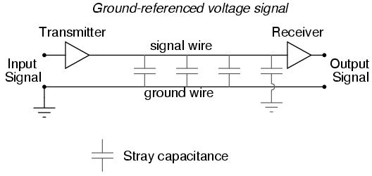
The general BogusBus design, where all bits are voltages referenced to a
common "ground" connection, is the worst-case situation for high-frequency
square wave data communication. Everything will work well for short
distances, where inductive and capacitive effects can be held to a minimum,
but for long distances this method will surely be problematic:
A robust alternative to the common ground signal method is the
differential voltage method, where each bit is represented by the
difference of voltage between a ground-isolated pair of wires, instead of a
voltage between one wire and a common ground. This tends to limit the
capacitive and inductive effects imposed upon each signal and the tendency
for the signals to be corrupted due to outside electrical interference,
thereby significantly improving the practical distance of a serial network:
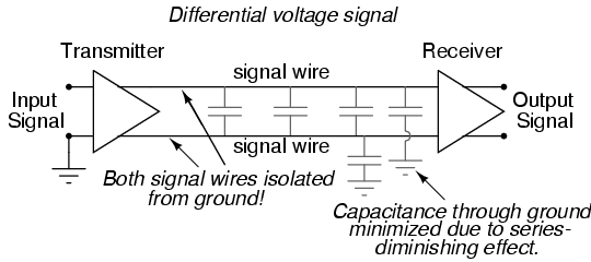
The triangular amplifier symbols represent differential amplifiers,
which output a voltage signal between two wires, neither one electrically
common with ground. Having eliminated any relation between the voltage
signal and ground, the only significant capacitance imposed on the signal
voltage is that existing between the two signal wires. Capacitance between a
signal wire and a grounded conductor is of much less effect, because the
capacitive path between the two signal wires via a ground connection is two
capacitances in series (from signal wire #1 to ground, then from ground to
signal wire #2), and series capacitance values are always less than any of
the individual capacitances. Furthermore, any "noise" voltage induced
between the signal wires and earth ground by an external source will be
ignored, because that noise voltage will likely be induced on both
signal wires in equal measure, and the receiving amplifier only responds to
the differential voltage between the two signal wires, rather than
the voltage between any one of them and earth ground.
RS-232C is a prime example of a ground-referenced serial network, while
RS-422A is a prime example of a differential voltage serial network. RS-232C
finds popular application in office environments where there is little
electrical interference and wiring distances are short. RS-422A is more
widely used in industrial applications where longer wiring distances and
greater potential for electrical interference from AC power wiring exists.
However, a large part of the problem with digital network signals is the
square-wave nature of such voltages, as was previously mentioned. If only we
could avoid square waves all together, we could avoid many of their inherent
difficulties in long, high-frequency networks. One way of doing this is to
modulate a sine wave voltage signal with our digital data.
"Modulation" means that magnitude of one signal has control over some aspect
of another signal. Radio technology has incorporated modulation for decades
now, in allowing an audio-frequency voltage signal to control either the
amplitude (AM) or frequency (FM) of a much higher frequency "carrier"
voltage, which is then send to the antenna for transmission. The
frequency-modulation (FM) technique has found more use in digital networks
than amplitude-modulation (AM), except that it's referred to as Frequency
Shift Keying (FSK). With simple FSK, sine waves of two distinct frequencies
are used to represent the two binary states, 1 and 0:
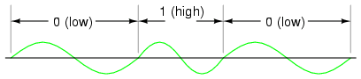
Due to the practical problems of getting the low/high frequency sine
waves to begin and end at the zero crossover points for any given
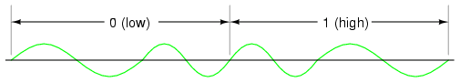
combination of 0's and 1's, a variation of FSK called phase-continuous FSK
is sometimes used, where the consecutive combination of a low/high
frequency represents one binary state and the combination of a high/low
frequency represents the other. This also makes for a situation where each
bit, whether it be 0 or 1, takes exactly the same amount of time to transmit
along the network:
With sine wave signal voltages, many of the problems encountered with
square wave digital signals are minimized, although the circuitry required
to modulate (and demodulate) the network signals is more complex and
expensive. |
