Specific resistance
Conductor ampacity rating is a crude
assessment of resistance based on the potential for current
to create a fire hazard. However, we may come across
situations where the voltage drop created by wire resistance
in a circuit poses concerns other than fire avoidance. For
instance, we may be designing a circuit where voltage across
a component is critical, and must not fall below a certain
limit. If this is the case, the voltage drops resulting from
wire resistance may cause an engineering problem while being
well within safe (fire) limits of ampacity:
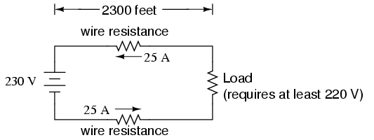
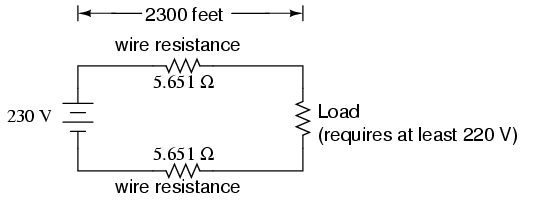
If the load in the above circuit will not
tolerate less than 220 volts, given a source voltage of 230
volts, then we'd better be sure that the wiring doesn't drop
more than 10 volts along the way. Counting both the supply
and return conductors of this circuit, this leaves a maximum
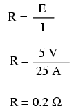
tolerable drop of 5 volts along the length of each wire.
Using Ohm's Law (R=E/I), we can determine the maximum
allowable resistance for each piece of wire:
We know that the wire length is 2300 feet
for each piece of wire, but how do we determine the amount
of resistance for a specific size and length of wire? To do
that, we need another formula:

This formula relates the resistance of a
conductor with its specific resistance (the Greek letter "rho"
(ρ), which looks similar to a lower-case letter "p"), its
length ("l"), and its cross-sectional area ("A"). Notice
that with the length variable on the top of the fraction,
the resistance value increases as the length increases
(analogy: it is more difficult to force liquid through a
long pipe than a short one), and decreases as
cross-sectional area increases (analogy: liquid flows easier
through a fat pipe than through a skinny one). Specific
resistance is a constant for the type of conductor material
being calculated.
The specific resistances of several
conductive materials can be found in the following table. We
find copper near the bottom of the table, second only to
silver in having low specific resistance (good
conductivity):
SPECIFIC RESISTANCE AT 20 DEGREES CELSIUS
Material     Element/Alloy       (ohm-cmil/ft)    (microohm-cm)
===============================================================
Nichrome ------ Alloy --------------- 675 ----------- 112.2
Nichrome V ---- Alloy --------------- 650 ----------- 108.1
Manganin ------ Alloy --------------- 290 ----------- 48.21
Constantan ---- Alloy --------------- 272.97 -------- 45.38
Steel* -------- Alloy --------------- 100 ----------- 16.62
Platinum ----- Element -------------- 63.16 --------- 10.5
Iron --------- Element -------------- 57.81 --------- 9.61
Nickel ------- Element -------------- 41.69 --------- 6.93
Zinc --------- Element -------------- 35.49 --------- 5.90
Molybdenum --- Element -------------- 32.12 --------- 5.34
Tungsten ----- Element -------------- 31.76 --------- 5.28
Aluminum ----- Element -------------- 15.94 --------- 2.650
Gold --------- Element -------------- 13.32 --------- 2.214
Copper ------- Element -------------- 10.09 --------- 1.678
Silver ------- Element -------------- 9.546 --------- 1.587
* = Steel alloy at 99.5 percent iron, 0.5 percent carbon
Notice that the figures for specific
resistance in the above table are given in the very strange
unit of "ohms-cmil/ft" (Ω-cmil/ft), This unit indicates what
units we are expected to use in the resistance formula (R=ρl/A).
In this case, these figures for specific resistance are
intended to be used when length is measured in feet and
cross-sectional area is measured in circular mils.
The metric unit for specific resistance is
the ohm-meter (Ω-m), or ohm-centimeter (Ω-cm), with 1.66243
x 10-9 Ω-meters per Ω-cmil/ft (1.66243 x 10⁻⁷
Ω-cm per Ω-cmil/ft). In the Ω-cm column of the table, the
figures are actually scaled as �Ω-cm due to their very small
magnitudes. For example, iron is listed as 9.61 �Ω-cm, which
could be represented as 9.61 x 10⁻⁶ Ω-cm.
When using the unit of Ω-meter for specific
resistance in the R=ρl/A formula, the length needs to be in
meters and the area in square meters. When using the unit of
Ω-centimeter (Ω-cm) in the same formula, the length needs to
be in centimeters and the area in square centimeters.
All these units for specific resistance are
valid for any material (Ω-cmil/ft, Ω-m, or Ω-cm). One might
prefer to use Ω-cmil/ft, however, when dealing with round
wire where the cross-sectional area is already known in
circular mils. Conversely, when dealing with odd-shaped
busbar or custom busbar cut out of metal stock, where only
the linear dimensions of length, width, and height are
known, the specific resistance units of Ω-meter or Ω-cm may
be more appropriate.
Going back to our example circuit, we were
looking for wire that had 0.2 Ω or less of resistance over a
length of 2300 feet. Assuming that we're going to use copper
wire (the most common type of electrical wire manufactured),
we can set up our formula as such:
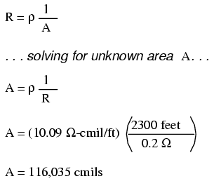
Algebraically solving for A, we get a value
of 116,035 circular mils. Referencing our solid wire size
table, we find that "double-ought" (2/0) wire with 133,100
cmils is adequate, whereas the next lower size,
"single-ought" (1/0), at 105,500 cmils is too small. Bear in
mind that our circuit current is a modest 25 amps. According
to our ampacity table for copper wire in free air, 14 gauge
wire would have sufficed (as far as not starting a
fire is concerned). However, from the standpoint of voltage
drop, 14 gauge wire would have been very unacceptable.
Just for fun, let's see what 14 gauge wire
would have done to our power circuit's performance. Looking
at our wire size table, we find that 14 gauge wire has a
cross-sectional area of 4,107 circular mils. If we're still
using copper as a wire material (a good choice, unless we're
really rich and can afford 4600 feet of 14 gauge
silver wire!), then our specific resistance will still be
10.09 Ω-cmil/ft:
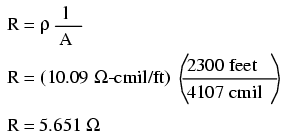
Remember that this is 5.651 Ω per 2300 feet
of 14-gauge copper wire, and that we have two runs of 2300
feet in the entire circuit, so each wire piece in the
circuit has 5.651 Ω of resistance:
Our total circuit wire resistance is 2 times
5.651, or 11.301 Ω. Unfortunately, this is far too
much resistance to allow 25 amps of current with a source
voltage of 230 volts. Even if our load resistance was 0 Ω,
our wiring resistance of 11.301 Ω would restrict the circuit
current to a mere 20.352 amps! As you can see, a "small"
amount of wire resistance can make a big difference in
circuit performance, especially in power circuits where the
currents are much higher than typically encountered in
electronic circuits.
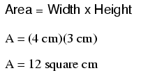
Let's do an example resistance problem for a
piece of custom-cut busbar. Suppose we have a piece of solid
aluminum bar, 4 centimeters wide by 3 centimeters tall by
125 centimeters long, and we wish to figure the end-to-end
resistance along the long dimension (125 cm). First, we
would need to determine the cross-sectional area of the bar:
We also need to know the specific resistance
of aluminum, in the unit proper for this application (Ω-cm).
From our table of specific resistances, we see that this is
2.65 x 10⁻⁶ Ω-cm. Setting up our R=ρl/A formula,
we have:
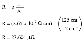
As you can see, the sheer thickness of a
busbar makes for very low resistances compared to
that of standard wire sizes, even when using a material with
a greater specific resistance.
The procedure for determining busbar
resistance is not fundamentally different than for
determining round wire resistance. We just need to make sure
that cross-sectional area is calculated properly and that
all the units correspond to each other as they should.
-
REVIEW:
-
Conductor resistance increases with
increased length and decreases with increased
cross-sectional area, all other factors being equal.
-
Specific Resistance ("ρ") is a
property of any conductive material, a figure used to
determine the end-to-end resistance of a conductor given
length and area in this formula: R = ρl/A
-
Specific resistance for materials are
given in units of Ω-cmil/ft or Ω-meters (metric).
Conversion factor between these two units is 1.66243 x 10⁻⁹
Ω-meters per Ω-cmil/ft, or 1.66243 x 10⁻⁷ Ω-cm
per Ω-cmil/ft.
-
If wiring voltage drop in a circuit is
critical, exact resistance calculations for the wires must
be made before wire size is chosen.
|
