Power dissipation
PARTS AND MATERIALS
The resistor values need not be exact, but
within five percent of the figures specified (+/- 0.5 Ω for
the 10 Ω resistor; +/- 16.5 Ω for the 330 Ω resistor). Color
codes for 5% tolerance 10 Ω and 330 Ω resistors are as
follows: Brown, Black, Black, Gold (10, +/- 5%), and Orange,
Orange, Brown, Gold (330, +/- 5%).
Do not use any battery size other than 6
volts for this experiment.
The thermometer should be as small as
possible, to facilitate rapid detection of heat produced by
the resistor. I recommend a medical thermometer, the type
used to take body temperature.
CROSS-REFERENCES
Lessons In Electric Circuits, Volume
1, chapter 2: "Ohm's Law"
LEARNING OBJECTIVES
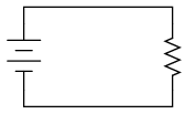
SCHEMATIC DIAGRAM
ILLUSTRATION
INSTRUCTIONS
Measure each resistor's resistance with your
ohmmeter, noting the exact values on a piece of paper for
later reference.
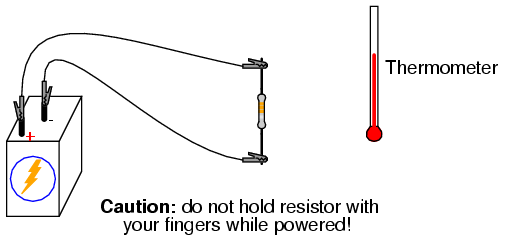
Connect the 330 Ω resistor to the 6 volt
battery using a pair of jumper wires as shown in the
illustration. Connect the jumper wires to the resistor
terminals before connecting the other ends to the
battery. This will ensure your fingers are not touching the
resistor when battery power is applied.
You might be wondering why I advise no
bodily contact with the powered resistor. This is because it
will become hot when powered by the battery. You will use
the thermometer to measure the temperature of each resistor
when powered.
With the 330 Ω resistor connected to the
battery, measure voltage with a voltmeter. In measuring
voltage, there is more than one way to obtain a proper
reading. Voltage may be measured directly across the
battery, or directly across the resistor. Battery voltage is
the same as resistor voltage in this circuit, since those
two components share the same set of electrically common
points: one side of the resistor is directly connected to
one side of the battery, and the other side of the resistor
is directly connected to the other side of the battery.
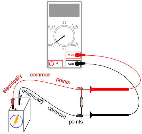
All points of contact along the upper wire
in the illustration (colored red) are electrically common to
each other. All points of contact along the lower wire
(colored black) are likewise electrically common to each
other. Voltage measured between any point on the upper wire
and any point on the lower wire should be the same. Voltage
measured between any two common points, however,
should be zero.
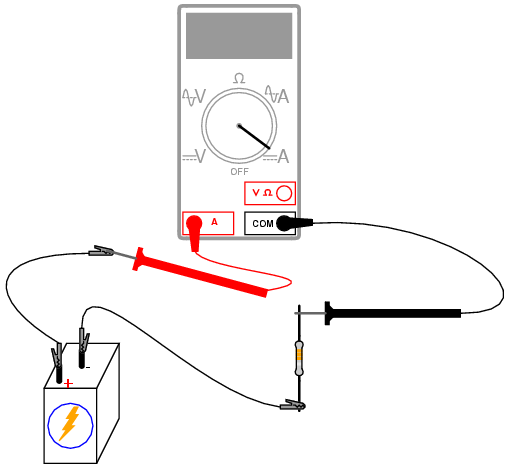
Using an ammeter, measure current through
the circuit. Again, there is no one "correct" way to measure
current, so long as the ammeter is placed within the
flow-path of electrons through the resistor and not
across a source of voltage. To do this, make a break in the
circuit, and place the ammeter within that break:
connect the two test probes to the two wire or terminal ends
left open from the break. One viable option is shown in the
following illustration:
Now that you've measured and recorded
resistor resistance, circuit voltage, and circuit current,
you are ready to calculate power dissipation. Whereas
voltage is the measure of electrical "push" motivating
electrons to move through a circuit, and current is the
measure of electron flow rate, power is the measure of
work-rate: how fast work is being done in the circuit.
It takes a certain amount of work to push electrons through
a resistance, and power is a description of how rapidly
that work is taking place. In mathematical equations, power
is symbolized by the letter "P" and measured in the unit of
the Watt (W).
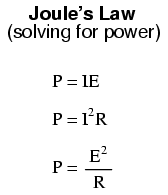
Power may be calculated by any one of three
equations -- collectively referred to as Joule's Law --
given any two out of three quantities of voltage, current,
and resistance:
Try calculating power in this circuit, using
the three measured values of voltage, current, and
resistance. Any way you calculate it, the power dissipation
figure should be roughly the same. Assuming a battery with
6.000 volts and a resistor of exactly 330 Ω, the power
dissipation will be 0.1090909 watts, or 109.0909 milli-watts
(mW), to use a metric prefix. Since the resistor has a power
rating of 1/4 watt (0.25 watts, or 250 mW), it is more than
capable of sustaining this level of power dissipation.
Because the actual power level is almost half the rated
power, the resistor should become noticeably warm but it
should not overheat. Touch the thermometer end to the
middle of the resistor and see how warm it gets.
The power rating of any electrical component
does not tell us how much power it will dissipate,
but simply how much power it may dissipate without
sustaining damage. If the actual amount of dissipated power
exceeds a component's power rating, that component will
increase temperature to the point of damage.
To illustrate, disconnect the 330 Ω resistor
and replace it with the 10 Ω resistor. Again, avoid touching
the resistor once the circuit is complete, as it will heat
up rapidly. The safest way to do this is to disconnect one
jumper wire from a battery terminal, then disconnect the 330
Ω resistor from the two alligator clips, then connect the 10
Ω resistor between the two clips, and finally reconnect the
jumper wire back to the battery terminal.
Caution: keep the 10 Ω resistor away from
any flammable materials when it is powered by the battery!
You may not have enough time to take voltage
and current measurements before the resistor begins to
smoke. At the first sign of distress, disconnect one of the
jumper wires from a battery terminal to interrupt circuit
current, and give the resistor a few moments to cool down.
With power still disconnected, measure the resistor's
resistance with an ohmmeter and note any substantial
deviation from its original value. If the resistor still
measures within +/- 5% of its advertised value (between 9.5
and 10.5 Ω), re-connect the jumper wire and let it smoke a
bit more.
What trend do you notice with the resistor's
value as it is damaged more and more by overpowering? It is
typical of resistors to fail with a greater-than-normal
resistance when overheated. This is often a self-protective
mode of failure, as an increased resistance results in less
current and (generally) less power dissipation, cooling it
down again. However, the resistor's normal resistance value
will not return if sufficiently damaged.
Performing some Joule's Law calculations for
resistor power again, we find that a 10 Ω resistor connected
to a 6 volt battery dissipates about 3.6 watts of power,
about 14.4 times its rated power dissipation. Little
wonder it smokes so quickly after connection to the battery!
|
