Introduction
Digital circuits are circuits dealing
with signals restricted to the extreme limits of zero and
some full amount. This stands in contrast to analog
circuits, in which signals are free to vary continuously
between the limits imposed by power supply voltage and
circuit resistances. These circuits find use in "true/false"
logical operations and digital computation.
The circuits in this chapter make use of
IC, or integrated circuit, components. Such
components are actually networks of interconnected
components manufactured on a single wafer of semiconducting
material. Integrated circuits providing a multitude of
pre-engineered functions are available at very low cost,
benefitting students, hobbyists and professional circuit
designers alike. Most integrated circuits provide the same
functionality as "discrete" semiconductor circuits at higher
levels of reliability and at a fraction of the cost.
Circuits in this chapter will primarily use
CMOS technology, as this form of IC design allows for
a broad range of power supply voltage while maintaining
generally low power consumption levels. Though CMOS
circuitry is susceptible to damage from static electricity
(high voltages will puncture the insulating barriers in the
MOSFET transistors), modern CMOS ICs are far more tolerant
of electrostatic discharge than the CMOS ICs of the past,
reducing the risk of chip failure by mishandling. Proper
handling of CMOS involves the use of anti-static foam for
storage and transport of IC's, and measures to prevent
static charge from building up on your body (use of a
grounding wrist strap, or frequently touching a grounded
object).
Circuits using TTL technology require
a regulated power supply voltage of 5 volts, and will not
tolerate any substantial deviation from this voltage level.
Any TTL circuits in this chapter will be adequately labeled
as such, and it will be expected that you realize its unique
power supply requirements.
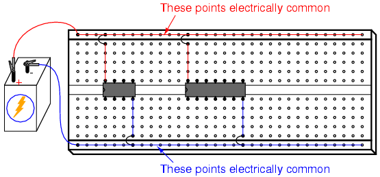
When building digital circuits using
integrated circuit "chips," it is highly recommended that
you use a breadboard with power supply "rail" connections
along the length. These are sets of holes in the breadboard
that are electrically common along the entire length of the
board. Connect one to the positive terminal of a battery,
and the other to the negative terminal, and DC power will be
available to any area of the breadboard via connection
through short jumper wires:
With so many of these integrated circuits
having "reset," "enable," and "disable" terminals needing to
be maintained in a "high" or "low" state, not to mention the
VDD (or VCC) and ground power
terminals which require connection to the power supply,
having both terminals of the power supply readily available
for connection at any point along the board's length is very
useful.
Most breadboards that I have seen have these
power supply "rail" holes, but some do not. Up until this
point, I've been illustrating circuits using a breadboard
lacking this feature, just to show how it isn't absolutely
necessary. However, digital circuits seem to require more
connections to the power supply than other types of
breadboard circuits, making this feature more than just a
convenience.
|
