Low-pass filters
By definition, a low-pass filter is a
circuit offering easy passage to low-frequency signals and
difficult passage to high-frequency signals. There are two
basic kinds of circuits capable of accomplishing this
objective, and many variations of each one:

The inductor's impedance increases with
increasing frequency. This high impedance in series tends to
block high-frequency signals from getting to the load. This
can be demonstrated with a SPICE analysis:
inductive lowpass filter
v1 1 0 ac 1 sin
l1 1 2 3
rload 2 0 1k
.ac lin 20 1 200
.plot ac v(2)
.end
freq       v(2)    0.2512      0.3981        0.631          1
- - - - - - - - - - - - - - - - - - - - - - - - - - - - - - -
1.000E+00  9.998E-01 .            .            .            *
1.147E+01  9.774E-01 .            .            .           *.
2.195E+01  9.240E-01 .            .            .          * .
3.242E+01  8.533E-01 .            .            .       *    .
4.289E+01  7.776E-01 .            .            .     *      .
5.337E+01  7.050E-01 .            .            .  *         .
6.384E+01  6.391E-01 .            .            *            .
7.432E+01  5.810E-01 .            .         *  .            .
8.479E+01  5.304E-01 .            .        *   .            .
9.526E+01  4.865E-01 .            .     *      .            .
1.057E+02  4.485E-01 .            .   *        .            .
1.162E+02  4.153E-01 .            .*           .            .
1.267E+02  3.863E-01 .           *.            .            .
1.372E+02  3.607E-01 .         *  .            .            .
1.476E+02  3.382E-01 .        *   .            .            .
1.581E+02  3.181E-01 .      *     .            .            .
1.686E+02  3.002E-01 .    *       .            .            .
1.791E+02  2.841E-01 .   *        .            .            .
1.895E+02  2.696E-01 . *          .            .            .
2.000E+02  2.564E-01 .*           .            .            .
- - - - - - - - - - - - - - - - - - - - - - - - - - - - - - -
Load voltage decreases with increasing frequency

The capacitor's impedance decreases with
increasing frequency. This low impedance in parallel with
the load resistance tends to short out high-frequency
signals, dropping most of the voltage gets across series
resistor R1.
capacitive lowpass filter
v1 1 0 ac 1 sin
r1 1 2 500
c1 2 0 7u
rload 2 0 1k
.ac lin 20 30 150
.plot ac v(2)
.end
freq       v(2)            0.3162     0.3981     0.5012  0.631
- - - - - - - - - - - - - - - - - - - - - - - - - - - - - - -
3.000E+01  6.102E-01 .        .         .         .        *.
3.632E+01  5.885E-01 .        .         .         .      *  .
4.263E+01  5.653E-01 .        .         .         .   *     .
4.895E+01  5.416E-01 .        .         .         .  *      .
5.526E+01  5.180E-01 .        .         .         .*        .
6.158E+01  4.948E-01 .        .         .        *.         .
6.789E+01  4.725E-01 .        .         .     *   .         .
7.421E+01  4.511E-01 .        .         .   *     .         .
8.053E+01  4.309E-01 .        .         . *       .         .
8.684E+01  4.118E-01 .        .         .*        .         .
9.316E+01  3.938E-01 .        .        *.         .         .
9.947E+01  3.770E-01 .        .      *  .         .         .
1.058E+02  3.613E-01 .        .    *    .         .         .
1.121E+02  3.465E-01 .        .  *      .         .         .
1.184E+02  3.327E-01 .        .*        .         .         .
1.247E+02  3.199E-01 .        *         .         .         .
1.311E+02  3.078E-01 .      * .         .         .         .
1.374E+02  2.965E-01 .    *   .         .         .         .
1.437E+02  2.859E-01 .  *     .         .         .         .
1.500E+02  2.760E-01 .*       .         .         .         .
- - - - - - - - - - - - - - - - - - - - - - - - - - - - - - -
                     Load voltage decreases with increasing frequency
The inductive low-pass filter is the
pinnacle of simplicity, with only one component comprising
the filter. The capacitive version of this filter is not
that much more complex, with only a resistor and capacitor
needed for operation. However, despite their increased
complexity, capacitive filter designs are generally
preferred over inductive because capacitors tend to be
"purer" reactive components than inductors and therefore are
more predictable in their behavior. By "pure" I mean that
capacitors exhibit little resistive effects than inductors,
making them almost 100% reactive. Inductors, on the other
hand, typically exhibit significant dissipative
(resistor-like) effects, both in the long lengths of wire
used to make them, and in the magnetic losses of the core
material. Capacitors also tend to participate less in
"coupling" effects with other components (generate and/or
receive interference from other components via mutual
electric or magnetic fields) than inductors, and are less
expensive.
However, the inductive low-pass filter is
often preferred in AC-DC power supplies to filter out the AC
"ripple" waveform created when AC is converted (rectified)
into DC, passing only the pure DC component. The primary
reason for this is the requirement of low filter resistance
for the output of such a power supply. A capacitive low-pass
filter requires an extra resistance in series with the
source, whereas the inductive low-pass filter does not. In
the design of a high-current circuit like a DC power supply
where additional series resistance is undesirable, the
inductive low-pass filter is the better design choice. On
the other hand, if low weight and compact size are higher
priorities than low internal supply resistance in a power
supply design, the capacitive low-pass filter might make
more sense.
All low-pass filters are rated at a certain
cutoff frequency. That is, the frequency above which
the output voltage falls below 70.7% of the input voltage.
This cutoff percentage of 70.7 is not really arbitrary, all
though it may seem so at first glance. In a simple
capacitive/resistive low-pass filter, it is the frequency at
which capacitive reactance in ohms equals resistance in
ohms. In a simple capacitive low-pass filter (one resistor,
one capacitor), the cutoff frequency is given as:
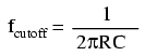
Inserting the values of R and C from the
last SPICE simulation into this formula, we arrive at a
cutoff frequency of 45.473 Hz. However, when we look at the
plot generated by the SPICE simulation, we see the load
voltage well below 70.7% of the source voltage (1 volt) even
at a frequency as low as 30 Hz, below the calculated cutoff
point. What's wrong? The problem here is that the load
resistance of 1 kΩ affects the frequency response of the
filter, skewing it down from what the formula told us it
would be. Without that load resistance in place, SPICE
produces a Bode plot whose numbers make more sense:
capacitive lowpass filter
v1 1 0 ac 1 sin
r1 1 2 500
c1 2 0 7u
* note: no load resistor!
.ac lin 20 40 50
.plot ac v(2)
.end
freq       v(2)    0.6607      0.6918       0.7244       0.7586
- - - - - - - - - - - - - - - - - - - - - - - - - - - - - - -
4.000E+01  7.508E-01 .           .             .          *  .
4.053E+01  7.465E-01 .           .             .        *    .
4.105E+01  7.423E-01 .           .             .      *      .
4.158E+01  7.380E-01 .           .             .     *       .
4.211E+01  7.338E-01 .           .             .   *         .
4.263E+01  7.295E-01 .           .             . *           .
4.316E+01  7.253E-01 .           .             *             .
4.368E+01  7.211E-01 .           .            *.             .
4.421E+01  7.170E-01 .           .          *  .             .
4.474E+01  7.129E-01 .           .        *    .             .
4.526E+01  7.087E-01 .           .      *      .             .
4.579E+01  7.046E-01 .           .     *       .             .
4.632E+01  7.006E-01 .           .   *         .             .
4.684E+01  6.965E-01 .           . *           .             .
4.737E+01  6.925E-01 .           *             .             .
4.789E+01  6.885E-01 .          *.             .             .
4.842E+01  6.846E-01 .        *  .             .             .
4.895E+01  6.806E-01 .      *    .             .             .
4.947E+01  6.767E-01 .    *      .             .             .
5.000E+01  6.728E-01 .   *       .             .             .
- - - - - - - - - - - - - - - - - - - - - - - - - - - - - - -
At 45.26 Hz, the output voltage is above 70.7 percent;
At 45.79 Hz, the output voltage is below 70.7 percent;
It should be exactly 70.7% at 45.473 Hz!
When dealing with filter circuits, it is
always important to note that the response of the filter
depends on the filter's component values and the
impedance of the load. If a cutoff frequency equation fails
to give consideration to load impedance, it assumes no load
and will fail to give accurate results for a real-life
filter conducting power to a load.
One frequent application of the capacitive
low-pass filter principle is in the design of circuits
having components or sections sensitive to electrical
"noise." As mentioned at the beginning of the last chapter,
sometimes AC signals can "couple" from one circuit to
another via capacitance (Cstray) and/or mutual
inductance (Mstray) between the two sets of
conductors. A prime example of this is unwanted AC signals
("noise") becoming impressed on DC power lines supplying
sensitive circuits:
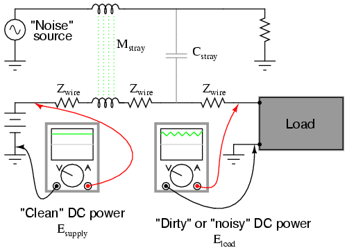
The oscilloscope-meter on the left shows the
"clean" power from the DC voltage source. After coupling
with the AC noise source via stray mutual inductance and
stray capacitance, though, the voltage as measured at the
load terminals is now a mix of AC and DC, the AC being
unwanted. Normally, one would expect Eload to be
precisely identical to Esource, because the
uninterrupted conductors connecting them should make the two
sets of points electrically common. However, power conductor
impedance allows the two voltages to differ, which means the
noise magnitude can vary at different points in the DC
system.
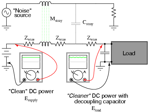
If we wish to prevent such "noise" from
reaching the DC load, all we need to do is connect a
low-pass filter near the load to block any coupled signals.
In its simplest form, this is nothing more than a capacitor
connected directly across the power terminals of the load,
the capacitor behaving as a very low impedance to any AC
noise, and shorting it out. Such a capacitor is called a
decoupling capacitor:
A cursory glance at a crowded
printed-circuit board (PCB) will typically reveal decoupling
capacitors scattered throughout, usually located as close as
possible to the sensitive DC loads. Capacitor size is
usually 0.1 �F or more, a minimum amount of capacitance
needed to produce a low enough impedance to short out any
noise. Greater capacitance will do a better job at filtering
noise, but size and economics limit decoupling capacitors to
meager values.
-
REVIEW:
-
A low-pass filter allows for easy passage
of low-frequency signals from source to load, and
difficult passage of high-frequency signals.
-
Inductive low-pass filters insert an
inductor in series with the load; capacitive low-pass
filters insert a resistor in series and a capacitor in
parallel with the load. The former filter design tries to
"block" the unwanted frequency signal while the latter
tries to short it out.
-
The cutoff frequency for a low-pass
filter is that frequency at which the output (load)
voltage equals 70.7% of the input (source) voltage. Above
the cutoff frequency, the output voltage is lower than
70.7% of the input, and visa-versa.
|
