Calculating power factor
As was mentioned before, the angle of this
"power triangle" graphically indicates the ratio between the
amount of dissipated (or consumed) power and the
amount of absorbed/returned power. It also happens to be the
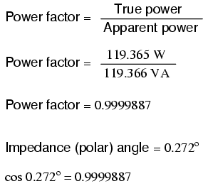
same angle as that of the circuit's impedance in polar form.
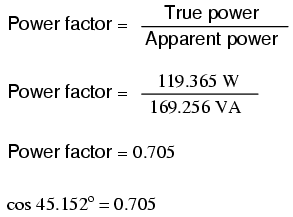
When expressed as a fraction, this ratio between true power
and apparent power is called the power factor for
this circuit. Because true power and apparent power form the
adjacent and hypotenuse sides of a right triangle,
respectively, the power factor ratio is also equal to the
cosine of that phase angle. Using values from the last
example circuit:
It should be noted that power factor, like
all ratio measurements, is a unitless quantity.
For the purely resistive circuit, the power
factor is 1 (perfect), because the reactive power equals
zero. Here, the power triangle would look like a horizontal
line, because the opposite (reactive power) side would have
zero length.
For the purely inductive circuit, the power
factor is zero, because true power equals zero. Here, the
power triangle would look like a vertical line, because the
adjacent (true power) side would have zero length.
The same could be said for a purely
capacitive circuit. If there are no dissipative (resistive)
components in the circuit, then the true power must be equal
to zero, making any power in the circuit purely reactive.
The power triangle for a purely capacitive circuit would
again be a vertical line (pointing down instead of up as it
was for the purely inductive circuit).
Power factor can be an important aspect to
consider in an AC circuit, because any power factor less
than 1 means that the circuit's wiring has to carry more
current than what would be necessary with zero reactance in
the circuit to deliver the same amount of (true) power to
the resistive load. If our last example circuit had been
purely resistive, we would have been able to deliver a full
169.256 watts to the load with the same 1.410 amps of
current, rather than the mere 119.365 watts that it is
presently dissipating with that same current quantity. The
poor power factor makes for an inefficient power delivery
system.
Poor power factor can be corrected,
paradoxically, by adding another load to the circuit drawing
an equal and opposite amount of reactive power, to cancel
out the effects of the load's inductive reactance. Inductive
reactance can only be canceled by capacitive reactance, so
we have to add a capacitor in parallel to our example
circuit as the additional load. The effect of these two
opposing reactances in parallel is to bring the circuit's
total impedance equal to its total resistance (to make the
impedance phase angle equal, or at least closer, to zero).
Since we know that the (uncorrected)
reactive power is 119.998 VAR (inductive), we need to
calculate the correct capacitor size to produce the same
quantity of (capacitive) reactive power. Since this
capacitor will be directly in parallel with the source (of
known voltage), we'll use the power formula which starts
from voltage and reactance:
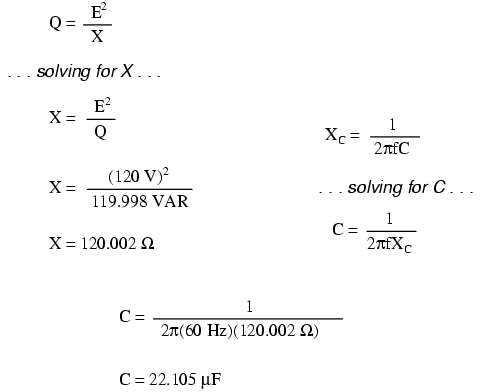
Let's use a rounded capacitor value of 22 �F
and see what happens to our circuit:
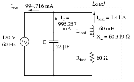
The power factor for the circuit, overall,
has been substantially improved. The main current has been
decreased from 1.41 amps to 994.7 milliamps, while the power
dissipated at the load resistor remains unchanged at 119.365
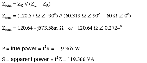
watts. The power factor is much closer to being 1:
Since the impedance angle is still a
positive number, we know that the circuit, overall, is still
more inductive than it is capacitive. If our power factor
correction efforts had been perfectly on-target, we would
have arrived at an impedance angle of exactly zero, or
purely resistive. If we had added too large of a capacitor
in parallel, we would have ended up with an impedance angle
that was negative, indicating that the circuit was more
capacitive than inductive.
It should be noted that too much capacitance
in an AC circuit will result in a low power factor just as
well as too much inductance. You must be careful not to
over-correct when adding capacitance to an AC circuit. You
must also be very careful to use the proper
capacitors for the job (rated adequately for power system
voltages and the occasional voltage spike from lightning
strikes, for continuous AC service, and capable of handling
the expected levels of current).
If a circuit is predominantly inductive, we
say that its power factor is lagging (because the
current wave for the circuit lags behind the applied voltage
wave). Conversely, if a circuit is predominantly capacitive,
we say that its power factor is leading. Thus, our
example circuit started out with a power factor of 0.705
lagging, and was corrected to a power factor of 0.999
lagging.
-
REVIEW:
-
Poor power factor in an AC circuit may be
``corrected,'' or re-established at a value close to 1, by
adding a parallel reactance opposite the effect of the
load's reactance. If the load's reactance is inductive in
nature (which is almost always will be), parallel
capacitance is what is needed to correct poor power
factor.
|
