Logic circuits, whether
comprised of electromechanical relays or solid-state gates, can be built in
many different ways to perform the same functions. There is usually no one
"correct" way to design a complex logic circuit, but there are usually ways
that are better than others.
In control systems, safety is (or at least should be) an important design
priority. If there are multiple ways in which a digital control circuit can
be designed to perform a task, and one of those ways happens to hold certain
advantages in safety over the others, then that design is the better one to
choose.
Let's take a look at a simple system and consider how it might be
implemented in relay logic. Suppose that a large laboratory or industrial
building is to be equipped with a fire alarm system, activated by any one of
several latching switches installed throughout the facility. The system
should work so that the alarm siren will energize if any one of the switches
is actuated. At first glance it seems as though the relay logic should be
incredibly simple: just use normally-open switch contacts and connect them
all in parallel with each other:
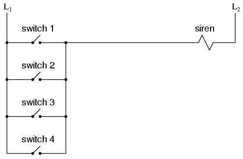
Essentially, this is the OR logic function implemented with four switch
inputs. We could expand this circuit to include any number of switch inputs,
each new switch being added to the parallel network, but I'll limit it to
four in this example to keep things simple. At any rate, it is an elementary
system and there seems to be little possibility of trouble.
Except in the event of a wiring failure, that is. The nature of electric
circuits is such that "open" failures (open switch contacts, broken wire
connections, open relay coils, blown fuses, etc.) are statistically more
likely to occur than any other type of failure. With that in mind, it makes
sense to engineer a circuit to be as tolerant as possible to such a failure.
Let's suppose that a wire connection for Switch #2 were to fail open:
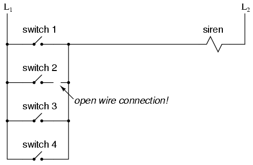
If this failure were to occur, the result would be that Switch #2 would no
longer energize the siren if actuated. This, obviously, is not good in a
fire alarm system. Unless the system were regularly tested (a good idea
anyway), no one would know there was a problem until someone tried to use
that switch in an emergency.
What if the system were re-engineered so as to sound the alarm in the
event of an open failure? That way, a failure in the wiring would result in
a false alarm, a scenario much more preferable than that of having a switch
silently fail and not function when needed. In order to achieve this design
goal, we would have to re-wire the switches so that an open contact
sounded the alarm, rather than a closed contact. That being the case,
the switches will have to be normally-closed and in series with each other,
powering a relay coil which then activates a normally-closed contact for the
siren:
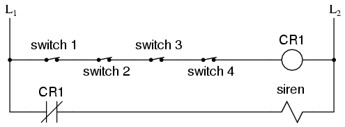
When all switches are unactuated (the regular operating state of this
system), relay CR1 will be energized, thus keeping contact CR1
open, preventing the siren from being powered. However, if any of the
switches are actuated, relay CR1 will de-energize, closing
contact CR1 and sounding the alarm. Also, if there is a break in
the wiring anywhere in the top rung of the circuit, the alarm will sound.
When it is discovered that the alarm is false, the workers in the facility
will know that something failed in the alarm system and that it needs to be
repaired.
Granted, the circuit is more complex than it was before the addition of
the control relay, and the system could still fail in the "silent" mode with
a broken connection in the bottom rung, but it's still a safer design than
the original circuit, and thus preferable from the standpoint of safety.
This design of circuit is referred to as fail-safe, due to its
intended design to default to the safest mode in the event of a common
failure such as a broken connection in the switch wiring. Fail-safe design
always starts with an assumption as to the most likely kind of wiring or
component failure, and then tries to configure things so that such a failure
will cause the circuit to act in the safest way, the "safest way" being
determined by the physical characteristics of the process.
Take for example an electrically-actuated (solenoid) valve for turning on
cooling water to a machine. Energizing the solenoid coil will move an armature
which then either opens or closes the valve mechanism, depending on what kind of
valve we specify. A spring will return the valve to its "normal" position when
the solenoid is de-energized. We already know that an open failure in the wiring
or solenoid coil is more likely than a short or any other type of failure, so we
should design this system to be in its safest mode with the solenoid
de-energized.
If it's cooling water we're controlling with this valve, chances are it is
safer to have the cooling water turn on in the event of a failure than to
shut off, the consequences of a machine running without coolant usually being
severe. This means we should specify a valve that turns on (opens up) when
de-energized and turns off (closes down) when energized. This may seem
"backwards" to have the valve set up this way, but it will make for a safer
system in the end.
One interesting application of fail-safe design is in the power generation
and distribution industry, where large circuit breakers need to be opened and
closed by electrical control signals from protective relays. If a 50/51 relay
(instantaneous and time overcurrent) is going to command a circuit breaker to
trip (open) in the event of excessive current, should we design it so that
the relay closes a switch contact to send a "trip" signal to the
breaker, or opens a switch contact to interrupt a regularly "on"
signal to initiate a breaker trip? We know that an open connection will be
the most likely to occur, but what is the safest state of the system: breaker
open or breaker closed?
At first, it would seem that it would be safer to have a large circuit
breaker trip (open up and shut off power) in the event of an open fault in
the protective relay control circuit, just like we had the fire alarm system
default to an alarm state with any switch or wiring failure. However, things
are not so simple in the world of high power. To have a large circuit breaker
indiscriminately trip open is no small matter, especially when customers are
depending on the continued supply of electric power to supply hospitals,
telecommunications systems, water treatment systems, and other important
infrastructures. For this reason, power system engineers have generally
agreed to design protective relay circuits to output a closed contact
signal (power applied) to open large circuit breakers, meaning that any open
failure in the control wiring will go unnoticed, simply leaving the breaker
in the status quo position.
Is this an ideal situation? Of course not. If a protective relay detects
an overcurrent condition while the control wiring is failed open, it will not
be able to trip open the circuit breaker. Like the first fire alarm system
design, the "silent" failure will be evident only when the system is needed.
However, to engineer the control circuitry the other way -- so that any open
failure would immediately shut the circuit breaker off, potentially blacking
out large potions of the power grid -- really isn't a better alternative.
An entire book could be written on the principles and practices of good
fail-safe system design. At least here, you know a couple of the
fundamentals: that wiring tends to fail open more often than shorted, and
that an electrical control system's (open) failure mode should be such that
it indicates and/or actuates the real-life process in the safest alternative
mode. These fundamental principles extend to non-electrical systems as well:
identify the most common mode of failure, then engineer the system so that
the probable failure mode places the system in the safest condition.
REVIEW: The goal of fail-safe design is to make a control system as
tolerant as possible to likely wiring or component failures. The most common type of wiring and component failure is an "open"
circuit, or broken connection. Therefore, a fail-safe system should be
designed to default to its safest mode of operation in the case of an open
circuit.
|
