Resistors
Because the relationship between voltage,
current, and resistance in any circuit is so regular, we can
reliably control any variable in a circuit simply by
controlling the other two. Perhaps the easiest variable in
any circuit to control is its resistance. This can be done
by changing the material, size, and shape of its conductive
components (remember how the thin metal filament of a lamp
created more electrical resistance than a thick wire?).
Special components called resistors
are made for the express purpose of creating a precise
quantity of resistance for insertion into a circuit. They
are typically constructed of metal wire or carbon, and
engineered to maintain a stable resistance value over a wide
range of environmental conditions. Unlike lamps, they do not
produce light, but they do produce heat as electric power is
dissipated by them in a working circuit. Typically, though,
the purpose of a resistor is not to produce usable heat, but
simply to provide a precise quantity of electrical
resistance.
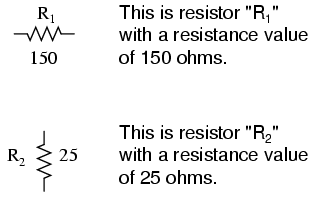
The most common schematic symbol for a
resistor is a zig-zag line:

Resistor values in ohms are usually shown as
an adjacent number, and if several resistors are present in
a circuit, they will be labeled with a unique identifier
number such as R1, R2, R3,
etc. As you can see, resistor symbols can be shown either
horizontally or vertically:
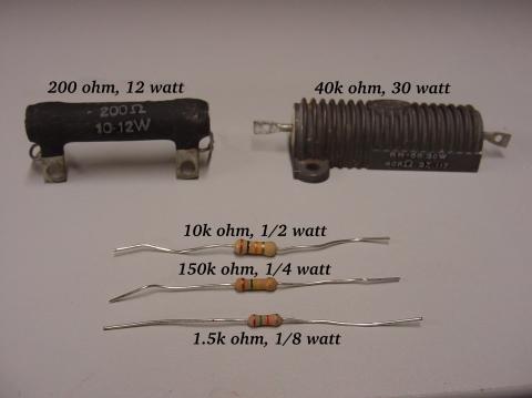
Real resistors look nothing like the zig-zag
symbol. Instead, they look like small tubes or cylinders
with two wires protruding for connection to a circuit. Here
is a sampling of different kinds and sizes of resistors:
In keeping more with their physical
appearance, an alternative schematic symbol for a resistor
looks like a small, rectangular box:

Resistors can also be shown to have varying
rather than fixed resistances. This might be for the purpose
of describing an actual physical device designed for the
purpose of providing an adjustable resistance, or it could
be to show some component that just happens to have an
unstable resistance:
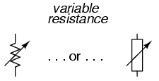
In fact, any time you see a component symbol
drawn with a diagonal arrow through it, that component has a
variable rather than a fixed value. This symbol "modifier"
(the diagonal arrow) is standard electronic symbol
convention.
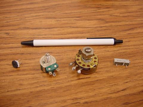
Variable resistors must have some physical
means of adjustment, either a rotating shaft or lever that
can be moved to vary the amount of electrical resistance.
Here is a photograph showing some devices called
potentiometers, which can be used as variable resistors:
Because resistors dissipate heat energy as
the electric currents through them overcome the "friction"
of their resistance, resistors are also rated in terms of
how much heat energy they can dissipate without overheating
and sustaining damage. Naturally, this power rating is
specified in the physical unit of "watts." Most resistors
found in small electronic devices such as portable radios
are rated at 1/4 (0.25) watt or less. The power rating of
any resistor is roughly proportional to its physical size.
Note in the first resistor photograph how the power ratings
relate with size: the bigger the resistor, the higher its
power dissipation rating. Also note how resistances (in
ohms) have nothing to do with size!
Although it may seem pointless now to have a
device doing nothing but resisting electric current,
resistors are extremely useful devices in circuits. Because
they are simple and so commonly used throughout the world of
electricity and electronics, we'll spend a considerable
amount of time analyzing circuits composed of nothing but
resistors and batteries.
For a practical illustration of resistors'
usefulness, examine the photograph below. It is a picture of
a printed circuit board, or PCB: an assembly
made of sandwiched layers of insulating phenolic fiber-board
and conductive copper strips, into which components may be
inserted and secured by a low-temperature welding process
called "soldering." The various components on this circuit
board are identified by printed labels. Resistors are
denoted by any label beginning with the letter "R".
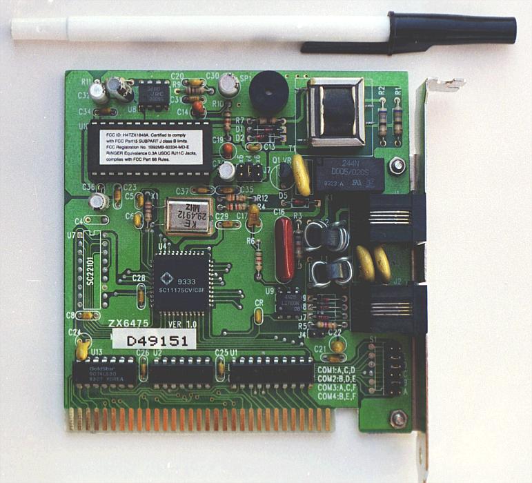
This particular circuit board is a computer
accessory called a "modem," which allows digital information
transfer over telephone lines. There are at least a dozen
resistors (all rated at 1/4 watt power dissipation) that can
be seen on this modem's board. Every one of the black
rectangles (called "integrated circuits" or "chips") contain
their own array of resistors for their internal functions,
as well.
Another circuit board example shows
resistors packaged in even smaller units, called "surface
mount devices." This particular circuit board is the
underside of a personal computer hard disk drive, and once
again the resistors soldered onto it are designated with
labels beginning with the letter "R":
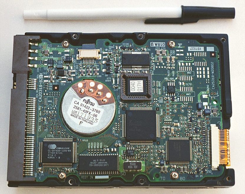
There are over one hundred surface-mount
resistors on this circuit board, and this count of course
does not include the number of resistors internal to the
black "chips." These two photographs should convince anyone
that resistors -- devices that "merely" oppose the flow of
electrons -- are very important components in the realm of
electronics!
In schematic diagrams, resistor symbols are
sometimes used to illustrate any general type of device in a
circuit doing something useful with electrical energy. Any
non-specific electrical device is generally called a load,
so if you see a schematic diagram showing a resistor symbol
labeled "load," especially in a tutorial circuit diagram
explaining some concept unrelated to the actual use of
electrical power, that symbol may just be a kind of
shorthand representation of something else more practical
than a resistor.
To summarize what we've learned in this
lesson, let's analyze the following circuit, determining all
that we can from the information given:
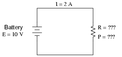
All we've been given here to start with is
the battery voltage (10 volts) and the circuit current (2
amps). We don't know the resistor's resistance in ohms or
the power dissipated by it in watts. Surveying our array of
Ohm's Law equations, we find two equations that give us
answers from known quantities of voltage and current:
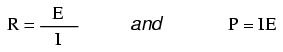
Inserting the known quantities of voltage
(E) and current (I) into these two equations, we can
determine circuit resistance (R) and power dissipation (P):
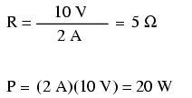
For the circuit conditions of 10 volts and 2
amps, the resistor's resistance must be 5 Ω. If we were
designing a circuit to operate at these values, we would
have to specify a resistor with a minimum power rating of 20
watts, or else it would overheat and fail.
-
REVIEW:
-
Devices called resistors are built
to provide precise amounts of resistance in electric
circuits. Resistors are rated both in terms of their
resistance (ohms) and their ability to dissipate heat
energy (watts).
-
Resistor resistance ratings cannot be
determined from the physical size of the resistor(s) in
question, although approximate power ratings can. The
larger the resistor is, the more power it can safely
dissipate without suffering damage.
-
Any device that performs some useful task
with electric power is generally known as a load.
Sometimes resistor symbols are used in schematic diagrams
to designate a non-specific load, rather than an actual
resistor.
|
