Quirks
"Garbage in, garbage out."
Anonymous
SPICE is a very reliable piece of software,
but it does have its little quirks that take some getting
used to. By "quirk" I mean a demand placed upon the user to
write the source file in a particular way in order for it to
work without giving error messages. I do not mean any
kind of fault with SPICE which would produce erroneous or
misleading results: that would be more properly referred to
as a "bug." Speaking of bugs, SPICE has a few of them as
well.
Some (or all) of these quirks may be unique
to SPICE version 2g6, which is the only version I've used
extensively. They may have been fixed in later versions.
A good beginning
SPICE demands that the source file begin
with something other than the first "card" in the circuit
description "deck." This first character in the source file
can be a linefeed, title line, or a comment: there just has
to be something there before the first
component-specifying line of the file. If not, SPICE will
refuse to do an analysis at all, claiming that there is a
serious error (such as improper node connections) in the
"deck."
A good ending
SPICE demands that the .end line at
the end of the source file not be terminated with a linefeed
or carriage return character. In other words, when you
finish typing ".end" you should not hit the
[Enter] key on your keyboard. The cursor on your text
editor should stop immediately to the right of the "d" after
the ".end" and go no further. Failure to heed this
quirk will result in a "missing .end card" error
message at the end of the analysis output. The actual
circuit analysis is not affected by this error, so I
normally ignore the message. However, if you're looking to
receive a "perfect" output, you must pay heed to this
idiosyncrasy.
Must have a node 0
You are given much freedom in numbering
circuit nodes, but you must have a node 0 somewhere
in your netlist in order for SPICE to work. Node 0 is the
default node for circuit ground, and it is the point of
reference for all voltages specified at single node
locations.
When simple DC analysis is performed by
SPICE, the output will contain a listing of voltages at all
non-zero nodes in the circuit. The point of reference
(ground) for all these voltage readings is node 0. For
example:
node    voltage    node     voltage
(  1)   15.0000    (  2)    0.6522
In this analysis, there is a DC voltage of
15 volts between node 1 and ground (node 0), and a DC
voltage of 0.6522 volts between node 2 and ground (node 0).
In both these cases, the voltage polarity is negative at
node 0 with reference to the other node (in other words,
both nodes 1 and 2 are positive with respect to node 0).
Avoid open circuits
SPICE cannot handle open circuits of any
kind. If your netlist specifies a circuit with an open
voltage source, for example, SPICE will refuse to perform an
analysis. A prime example of this type of error is found
when "connecting" a voltage source to the input of a
voltage-dependent source (used to simulate an operational
amplifier). SPICE needs to see a complete path for current,
so I usually tie a high-value resistor (call it rbogus!)
across the voltage source to act as a minimal load.
Avoid certain component loops
SPICE cannot handle certain uninterrupted
loops of components in a circuit, namely voltage sources and
inductors. The following loops will cause SPICE to abort
analysis:

netlist
l1 2 4 10m
l2 2 4 50m
l3 2 4 25m

netlist
v1 1 0 dc 12
l1 1 0 150m

netlist
c1 5 6 33u
c2 6 7 47u
The reason SPICE can't handle these
conditions stems from the way it performs DC analysis: by
treating all inductors as shorts and all capacitors as
opens. Since short-circuits (0 Ω) and open circuits
(infinite resistance) either contain or generate
mathematical infinitudes, a computer simply cannot deal with
them, and so SPICE will discontinue analysis if any of these
conditions occur.
In order to make these component
configurations acceptable to SPICE, you must insert
resistors of appropriate values into the appropriate places,
eliminating the respective short-circuits and open-circuits.
If a series resistor is required, choose a very low
resistance value. Conversely, if a parallel resistor is
required, choose a very high resistance value. For example:
To fix the parallel inductor problem, insert
a very low-value resistor in series with each offending
inductor.

original netlist
l1 2 4 10m
l2 2 4 50m
l3 2 4 25m
fixed netlist
rbogus1 2 3 1e-12
rbogus2 2 5 1e-12
l1 3 4 10m
l2 2 4 50m
l3 5 4 25m
The extremely low-resistance resistors Rbogus1
and Rbogus2 (each one with a mere 1 pico-ohm of
resistance) "break up" the direct parallel connections that
existed between L1, L2, and L3.
It is important to choose very low resistances here so that
circuit operation is not substantially impacted by the
"fix."
To fix the voltage source / inductor loop,
insert a very low-value resistor in series with the two
components.

original netlist
v1 1 0 dc 12
l1 1 0 150m
fixed netlist
v1 1 0 dc 12
l1 2 0 150m
rbogus 1 2 1e-12
As in the previous example with parallel
inductors, it is important to make the correction resistor (Rbogus)
very low in resistance, so as to not substantially impact
circuit operation.
To fix the series capacitor circuit, one of
the capacitors must have a resistor shunting across it.
SPICE requires a DC current path to each capacitor for
analysis.

original netlist
c1 5 6 33u
c2 6 7 47u
fixed netlist
c1 5 6 33u
c2 6 7 47u
rbogus 6 7 9e12
The Rbogus value of 9 Tera-ohms
provides a DC current path to C1 (and around C2)
without substantially impacting the circuit's operation.
Current measurement
Although printing or plotting of voltage is
quite easy in SPICE, the output of current values is a bit
more difficult. Voltage measurements are specified by
declaring the appropriate circuit nodes. For example, if we
desire to know the voltage across a capacitor whose leads
connect between nodes 4 and 7, we might make out .print
statement look like this:

c1 4 7 22u
.print ac v(4,7)
However, if we wanted to have SPICE measure
the current through that capacitor, it wouldn't be
quite so easy. Currents in SPICE must be specified in
relation to a voltage source, not any arbitrary component.
For example:

c1 4 7 22u
vinput 6 4 ac 1 sin
.print ac i(vinput)
This .print card instructs SPICE to
print the current through voltage source Vinput,
which happens to be the same as the current through our
capacitor between nodes 4 and 7. But what if there is no
such voltage source in our circuit to reference for current
measurement? One solution is to insert a shunt resistor into
the circuit and measure voltage across it. In this case, I
have chosen a shunt resistance value of 1 Ω to produce 1
volt per amp of current through C1:

c1 4 7 22u
rshunt 6 4 1
.print ac v(6,4)
However, the insertion of an extra
resistance into our circuit large enough to drop a
meaningful voltage for the intended range of current might
adversely affect things. A better solution for SPICE is
this, although one would never seek such a current
measurement solution in real life:

c1 4 7 22u
vbogus 6 4 dc 0
.print ac i(vbogus)
Inserting a "bogus" DC voltage source of
zero volts doesn't affect circuit operation at all, yet it
provides a convenient place for SPICE to take a current
measurement. Interestingly enough, it doesn't matter that Vbogus
is a DC source when we're looking to measure AC current! The
fact that SPICE will output an AC current reading is
determined by the "ac" specification in the
.print card and nothing more.
It should also be noted that the way SPICE
assigns a polarity to current measurements is a bit odd.
Take the following circuit as an example:
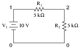
example
v1 1 0
r1 1 2 5k
r2 2 0 5k
.dc v1 10 10 1
.print dc i(v1)
.end
With 10 volts total voltage and 10 kΩ total
resistance, you might expect SPICE to tell you there's going
to be 1 mA (1e-03) of current through voltage source V1,
but in actuality SPICE will output a figure of negative
1 mA (-1e-03)! SPICE regards current out of the negative end
of a DC voltage source (the normal direction) to be a
negative value of current rather than a positive value of
current. There are times I'll throw in a "bogus" voltage
source in a DC circuit like this simply to get SPICE to
output a positive current value:

example
v1 1 0
r1 1 2 5k
r2 2 3 5k
vbogus 3 0 dc 0
.dc v1 10 10 1
.print dc i(vbogus)
.end
Notice how Vbogus is positioned
so that the circuit current will enter its positive side
(node 3) and exit its negative side (node 0). This
orientation will ensure a positive output figure for circuit
current.
Fourier analysis
When performing a Fourier (frequency-domain)
analysis on a waveform, I have found it necessary to either
print or plot the waveform using the .print or
.plot cards, respectively. If you don't print or plot
it, SPICE will pause for a moment during analysis and then
abort the job after outputting the "initial transient
solution."
Also, when analyzing a square wave produced
by the "pulse" source function, you must give the
waveform some finite rise and fall time, or else the Fourier
analysis results will be incorrect. For some reason, a
perfect square wave with zero rise/fall time produces
significant levels of even harmonics according to
SPICE's Fourier analysis option, which is not true for real
square waves. |
