AC instrumentation transducers
Just as devices have been made to measure
certain physical quantities and repeat that information in
the form of DC electrical signals (thermocouples, strain
gauges, pH probes, etc.), special devices have been made
that do the same with AC.
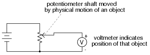
It is often necessary to be able to detect
and transmit the physical position of mechanical parts via
electrical signals. This is especially true in the fields of
automated machine tool control and robotics. A simple and
easy way to do this is with a potentiometer:
However, potentiometers have their own
unique problems. For one, they rely on physical contact
between the "wiper" and the resistance strip, which means
they suffer the effects of physical wear over time. As
potentiometers wear, their proportional output versus shaft
position becomes less and less certain. You might have
already experienced this effect when adjusting the volume
control on an old radio: when twisting the knob, you might
hear "scratching" sounds coming out of the speakers. Those
noises are the result of poor wiper contact in the volume
control potentiometer.
Also, this physical contact between wiper
and strip creates the possibility of arcing (sparking)
between the two as the wiper is moved. With most
potentiometer circuits, the current is so low that wiper
arcing is negligible, but it is a possibility to be
considered. If the potentiometer is to be operated in an
environment where combustible vapor or dust is present, this
potential for arcing translates into a potential for an
explosion!
Using AC instead of DC, we are able to
completely avoid sliding contact between parts if we use a
variable transformer instead of a potentiometer.
Devices made for this purpose are called LVDT's, which
stands for Linear Variable Differential
Transformers. The design of an LVDT looks like this:

Obviously, this device is a transformer:
it has a single primary winding powered by an external
source of AC voltage, and two secondary windings connected
in series-bucking fashion. It is variable because the
core is free to move between the windings. It is
differential because of the way the two secondary
windings are connected. Being arranged to oppose each other
(180o out of phase) means that the output of this
device will be the difference between the voltage
output of the two secondary windings. When the core is
centered and both windings are outputting the same voltage,
the net result at the output terminals will be zero volts.
It is called linear because the core's freedom of
motion is straight-line.
The AC voltage output by an LVDT indicates
the position of the movable core. Zero volts means that the
core is centered. The further away the core is from center
position, the greater percentage of input ("excitation")
voltage will be seen at the output. The phase of the output
voltage relative to the excitation voltage indicates which
direction from center the core is offset.
The primary advantage of an LVDT over a
potentiometer for position sensing is the absence of
physical contact between the moving and stationary parts.
The core does not contact the wire windings, but slides in
and out within a nonconducting tube. Thus, the LVDT does not
"wear" like a potentiometer, nor is there the possibility of
creating an arc.
Excitation of the LVDT is typically 10 volts
RMS or less, at frequencies ranging from power line to the
high audio (20 kHz) range. One potential disadvantage of the
LVDT is its response time, which is mostly dependent on the
frequency of the AC voltage source. If very quick response
times are desired, the frequency must be higher to allow
whatever voltage-sensing circuits enough cycles of AC to
determine voltage level as the core is moved. To illustrate
the potential problem here, imagine this exaggerated
scenario: an LVDT powered by a 60 Hz voltage source, with
the core being moved in and out hundreds of times per
second. The output of this LVDT wouldn't even look like a
sine wave because the core would be moved throughout its
range of motion before the AC source voltage could complete
a single cycle! It would be almost impossible to determine
instantaneous core position if it moves faster than the
instantaneous source voltage does.
A variation on the LVDT is the RVDT, or Rotary
Variable Differential Transformer. This
device works on almost the same principle, except that the
core revolves on a shaft instead of moving in a straight
line. RVDT's can be constructed for limited motion of 360o
(full-circle) motion.
Continuing with this principle, we have what
is known as a Synchro or Selsyn, which is a
device constructed a lot like a wound-rotor polyphase AC
motor or generator. The rotor is free to revolve a full 360o,
just like a motor. On the rotor is a single winding
connected to a source of AC voltage, much like the primary
winding of an LVDT. The stator windings are usually in the
form of a three-phase Y, although synchros with more than
three phases have been built:

Voltages induced in the stator windings from
the rotor's AC excitation are not phase-shifted by
120o as in a real three-phase generator. If the
rotor were energized with DC current rather than AC and the
shaft spun continuously, then the voltages would be true
three-phase. But this is not how a synchro is designed to be
operated. Rather, this is a position-sensing device
much like an RVDT, except that its output signal is much
more definite. With the rotor energized by AC, the stator
winding voltages will be proportional in magnitude to the
angular position of the rotor, phase either 0o or
180o shifted, like a regular LVDT or RVDT. You
could think of it as a transformer with one primary winding
and three secondary windings, each secondary winding
oriented at a unique angle. As the rotor is slowly turned,
each winding in turn will line up directly with the rotor,
producing full voltage, while the other windings will
produce something less than full voltage.
Synchros are often used in pairs. With their
rotors connected in parallel and energized by the same AC
voltage source, their shafts will match position to a high
degree of accuracy:
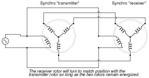
Such "transmitter/receiver" pairs have been
used on ships to relay rudder position, or to relay
navigational gyro position over fairly long distances. The
only difference between the "transmitter" and the "receiver"
is which one gets turned by an outside force. The "receiver"
can just as easily be used as the "transmitter" by forcing
its shaft to turn and letting the synchro on the left match
position.
If the receiver's rotor is left unpowered,
it will act as a position-error detector, generating an AC
voltage at the rotor if the shaft is anything other than 90o
or 270o shifted from the shaft position of the
transmitter. The receiver rotor will no longer generate any
torque and consequently will no longer automatically match
position with the transmitter's:
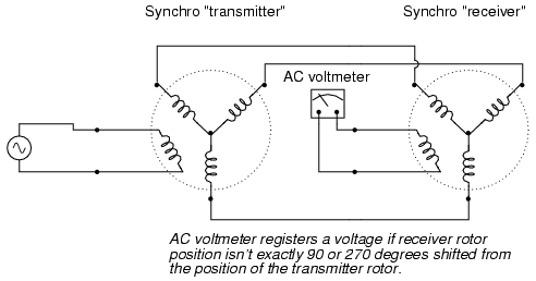
This can be thought of almost as a sort of
bridge circuit that achieves balance only if the receiver
shaft is brought to one of two (matching) positions with the
transmitter shaft.
One rather ingenious application of the
synchro is in the creation of a phase-shifting device,
provided that the stator is energized by three-phase AC:
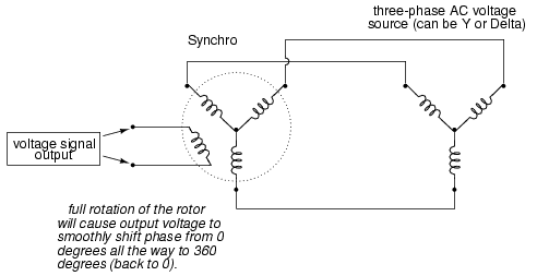
As the synchro's rotor is turned, the rotor
coil will progressively align with each stator coil, their
respective magnetic fields being 120o
phase-shifted from one another. In between those positions,
these phase-shifted fields will mix to produce a rotor
voltage somewhere between 0o, 120o, or
240o shift. The practical result is a device
capable of providing an infinitely variable-phase AC voltage
with the twist of a knob (attached to the rotor shaft).
So far the transducers discussed have all
been of the inductive variety. However, it is possible to
make transducers which operate on variable capacitance as
well, AC being used to sense the change in capacitance and
generate a variable output voltage.
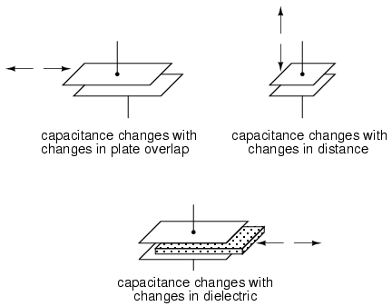
Remember that the capacitance between two
conductive surfaces varies with three major factors: the
overlapping area of those two surfaces, the distance between
them, and the dielectric constant of the material in between
the surfaces. If two out of three of these variables can be
fixed (stabilized) and the third allowed to vary, then any
measurement of capacitance between the surfaces will be
solely indicative of changes in that third variable.
Medical researchers have long made use of
capacitive sensing to detect physiological changes in living
bodies. As early as 1907, a German researcher named H.
Cremer placed two metal plates on either side of a beating
frog heart and measured the capacitance changes resulting
from the heart alternately filling and emptying itself of
blood. Similar measurements have been performed on human
beings with metal plates placed on the chest and back,
recording respiratory and cardiac action by means of
capacitance changes. For more precise capacitive
measurements of organ activity, metal probes have been
inserted into organs (especially the heart) on the tips of
catheter tubes, capacitance being measured between the metal
probe and the body of the subject. With a sufficiently high
AC excitation frequency and sensitive enough voltage
detector, not just the pumping action but also the sounds
of the active heart may be readily interpreted.
Like inductive transducers, capacitive
transducers can also be made to be self-contained units,
unlike the direct physiological examples described above.
Some transducers work by making one of the capacitor plates
movable, either in such a way as to vary the overlapping
area or the distance between the plates. Other transducers
work by moving a dielectric material in and out between two
fixed plates:
Transducers with greater sensitivity and
immunity to changes in other variables can be obtained by
way of differential design, much like the concept behind the
LVDT (Linear Variable Differential Transformer). Here
are a few examples of differential capacitive transducers:
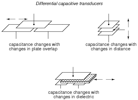
As you can see, all of the differential
devices shown in the above illustration have three
wire connections rather than two: one wire for each of the
"end" plates and one for the "common" plate. As the
capacitance between one of the "end" plates and the "common"
plate changes, the capacitance between the other "end" plate
and the "common" plate is such to change in the opposite
direction. This kind of transducer lends itself very well to
implementation in a bridge circuit:
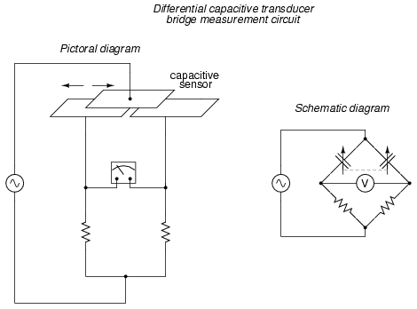
Capacitive transducers provide relatively
small capacitances for a measurement circuit to operate
with, typically in the picofarad range. Because of
this, high power supply frequencies (in the megahertz
range!) are usually required to reduce these capacitive
reactances to reasonable levels. Given the small
capacitances provided by typical capacitive transducers,
stray capacitances have the potential of being major sources
of measurement error. Good conductor shielding is
essential for reliable and accurate capacitive
transducer circuitry!
The bridge circuit is not the only way to
effectively interpret the differential capacitance output of
such a transducer, but it is one of the simplest to
implement and understand. As with the LVDT, the voltage
output of the bridge is proportional to the displacement of
the transducer action from its center position, and the
direction of offset will be indicated by phase shift. This
kind of bridge circuit is similar in function to the kind
used with strain gauges: it is not intended to be in a
"balanced" condition all the time, but rather the degree of
imbalance represents the magnitude of the quantity being
measured.
An interesting alternative to the bridge
circuit for interpreting differential capacitance is the
twin-T. It requires the use of diodes, those "one-way
valves" for electric current mentioned earlier in the
chapter:
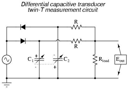
This circuit might be better understood if
re-drawn to resemble more of a bridge configuration:
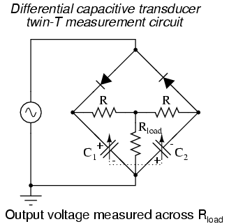
Capacitor C1 is charged by the AC
voltage source during every positive half-cycle (positive as
measured in reference to the ground point), while C2
is charged during every negative half-cycle. While one
capacitor is being charged, the other capacitor discharges
(at a slower rate than it was charged) through the
three-resistor network. As a consequence, C1
maintains a positive DC voltage with respect to ground, and
C2 a negative DC voltage with respect to ground.
If the capacitive transducer is displaced
from center position, one capacitor will increase in
capacitance while the other will decrease. This has little
effect on the peak voltage charge of each capacitor, as
there is negligible resistance in the charging current path
from source to capacitor, resulting in a very short time
constant (τ). However, when it comes time to discharge
through the resistors, the capacitor with the greater
capacitance value will hold its charge longer, resulting in
a greater average DC voltage over time than the lesser-value
capacitor.
The load resistor (Rload),
connected at one end to the point between the two
equal-value resistors (R) and at the other end to ground,
will drop no DC voltage if the two capacitors' DC voltage
charges are equal in magnitude. If, on the other hand, one
capacitor maintains a greater DC voltage charge than the
other due to a difference in capacitance, the load resistor
will drop a voltage proportional to the difference between
these voltages. Thus, differential capacitance is translated
into a DC voltage across the load resistor.
Across the load resistor, there is both AC
and DC voltage present, with only the DC voltage being
significant to the difference in capacitance. If desired, a
low-pass filter may be added to the output of this circuit
to block the AC, leaving only a DC signal to be interpreted
by measurement circuitry:

As a measurement circuit for differential
capacitive sensors, the twin-T configuration enjoys many
advantages over the standard bridge configuration. First and
foremost, transducer displacement is indicated by a simple
DC voltage, not an AC voltage whose magnitude and
phase must be interpreted to tell which capacitance is
greater. Furthermore, given the proper component values and
power supply output, this DC output signal may be strong
enough to directly drive an electromechanical meter
movement, eliminating the need for an amplifier circuit.
Another important advantage is that all important circuit
elements have one terminal directly connected to ground: the
source, the load resistor, and both capacitors are all
ground-referenced. This helps minimize the ill effects of
stray capacitance commonly plaguing bridge measurement
circuits, likewise eliminating the need for compensatory
measures such as the Wagner earth.
This circuit is also easy to specify parts
for. Normally, a measurement circuit incorporating
complementary diodes requires the selection of "matched"
diodes for good accuracy. Not so with this circuit! So long
as the power supply voltage is significantly greater than
the deviation in voltage drop between the two diodes, the
effects of mismatch are minimal and contribute little to
measurement error. Furthermore, supply frequency variations
have a relatively low impact on gain (how much output
voltage is developed for a given amount of transducer
displacement), and square-wave supply voltage works as well
as sine-wave, assuming a 50% duty cycle (equal positive and
negative half-cycles), of course.
Personal experience with using this circuit
has confirmed its impressive performance. Not only is it
easy to prototype and test, but its relative insensitivity
to stray capacitance and its high output voltage as compared
to traditional bridge circuits makes it a very robust
alternative. |
