High-impedance voltmeter
PARTS AND MATERIALS
-
Operational amplifier, model TL082
recommended (Radio Shack catalog # 276-1715)
-
Operational amplifier, model LM1458
recommended (Radio Shack catalog # 276-038)
-
Four 6 volt batteries
-
One meter movement, 1 mA full-scale
deflection (Radio Shack catalog #22-410)
-
15 kΩ precision resistor
-
Four 1 MΩ resistors
The 1 mA meter movement sold by Radio Shack
is advertised as a 0-15 VDC meter, but is actually a 1 mA
movement sold with a 15 kΩ +/- 1% tolerance multiplier
resistor. If you get this Radio Shack meter movement, you
can use the included 15 kΩ resistor for the resistor
specified in the parts list.
This meter experiment is based on a JFET-input
op-amp such as the TL082. The other op-amp (model 1458) is
used in this experiment to demonstrate the absence of
latch-up: a problem inherent to the TL082.
You don't need 1 MΩ resistors, exactly.
Any very high resistance resistors will suffice.
CROSS-REFERENCES
Lessons In Electric Circuits, Volume
3, chapter 8: "Operational Amplifiers"
LEARNING OBJECTIVES
-
Voltmeter loading: its causes and its
solution
-
How to make a high-impedance voltmeter
using an op-amp
-
What op-amp "latch-up" is and how to avoid
it
SCHEMATIC DIAGRAM
ILLUSTRATION
INSTRUCTIONS
An ideal voltmeter has infinite input
impedance, meaning that it draws zero current from the
circuit under test. This way, there will be no "impact" on
the circuit as the voltage is being measured. The more
current a voltmeter draws from the circuit under test, the
more the measured voltage will "sag" under the loading
effect of the meter, like a tire-pressure gauge releasing
air out of the tire being measured: the more air released
from the tire, the more the tire's pressure will be impacted
in the act of measurement. This loading is more pronounced
on circuits of high resistance, like the voltage divider
made of 1 MΩ resistors, shown in the schematic diagram.
If you were to build a simple 0-15 volt
range voltmeter by connecting the 1 mA meter movement in
series with the 15 kΩ precision resistor, and try to use
this voltmeter to measure the voltages at TP1, TP2, or TP3
(with respect to ground), you'd encounter severe
measurement errors induced by meter "impact:"
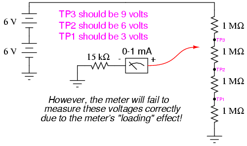
Try using the meter movement and 15 kΩ
resistor as shown to measure these three voltages. Does the
meter read falsely high or falsely low? Why do you think
this is?
If we were to increase the meter's input
impedance, we would diminish its current draw or "load" on
the circuit under test and consequently improve its
measurement accuracy. An op-amp with high-impedance inputs
(using a JFET transistor input stage rather than a BJT input
stage) works well for this application.
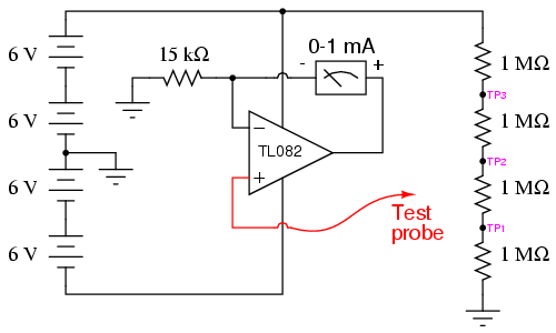
Note that the meter movement is part of the
op-amp's feedback loop from output to inverting input. This
circuit drives the meter movement with a current
proportional to the voltage impressed at the noninverting
(+) input, the requisite current supplied directly from the
batteries through the op-amp's power supply pins, not from
the circuit under test through the test probe. The meter's
range is set by the resistor connecting the inverting (-)
input to ground.
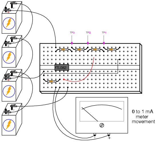
Build the op-amp meter circuit as shown and
re-take voltage measurements at TP1, TP2, and TP3. You
should enjoy far better success this time, with the meter
movement accurately measuring these voltages (approximately
3, 6, and 9 volts, respectively).
You may witness the extreme sensitivity of
this voltmeter by touching the test probe with one hand and
the most positive battery terminal with the other. Notice
how you can drive the needle upward on the scale simply by
measuring battery voltage through your body resistance: an
impossible feat with the original, unamplified voltmeter
circuit. If you touch the test probe to ground, the meter
should read exactly 0 volts.
After you've proven this circuit to work,
modify it by changing the power supply from dual to split.
This entails removing the center-tap ground connection
between the 2nd and 3rd batteries, and grounding the far
negative battery terminal instead:
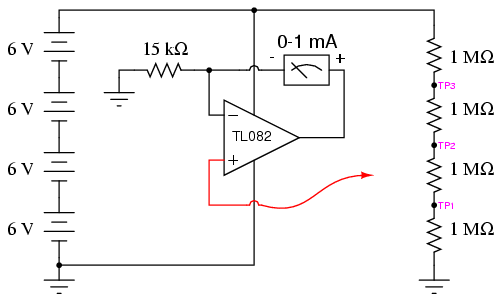
This alteration in the power supply
increases the voltages at TP1, TP2, and TP3 to 6, 12, and 18
volts, respectively. With a 15 kΩ range resistor and a 1 mA
meter movement, measuring 18 volts will gently "peg" the
meter, but you should be able to measure the 6 and 12 volt
test points just fine.
Try touching the meter's test probe to
ground. This should drive the meter needle to exactly
0 volts as before, but it will not! What is happening here
is an op-amp phenomenon called latch-up: where the
op-amp output drives to a positive voltage when the input
common-mode voltage exceeds the allowable limit. In this
case, as with many JFET-input op-amps, neither input should
be allowed to come close to either power supply rail
voltage. With a single supply, the op-amp's negative power
rail is at ground potential (0 volts), so grounding the test
probe brings the noninverting (+) input exactly to that rail
voltage. This is bad for a JFET op-amp, and drives the
output strongly positive, even though it doesn't seem like
it should, based on how op-amps are supposed to function.
When the op-amp ran on a "dual" supply
(+12/-12 volts, rather than a "single" +24 volt supply), the
negative power supply rail was 12 volts away from ground (0
volts), so grounding the test probe didn't violate the
op-amp's common-mode voltage limit. However, with the
"single" +24 volt supply, we have a problem. Note that some
op-amps do not "latch-up" the way the model TL082 does. You
may replace the TL082 with an LM1458 op-amp, which is
pin-for-pin compatible (no breadboard wiring changes
needed). The model 1458 will not "latch-up" when the test
probe is grounded, although you may still get incorrect
meter readings with the measured voltage exactly equal to
the negative power supply rail. As a general rule, you
should always be sure the op-amp's power supply rail
voltages exceed the expected input voltages. |
