Circuit effects
The principle of non-sinusoidal, repeating
waveforms being equivalent to a series of sine waves at
different frequencies is a fundamental property of waves in
general and it has great practical import in the study of AC
circuits. It means that any time we have a waveform that
isn't perfectly sine-wave-shaped, the circuit in question
will react as though it's having an array of different
frequency voltages imposed on it at once.
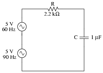
When an AC circuit is subjected to a source
voltage consisting of a mixture of frequencies, the
components in that circuit respond to each constituent
frequency in a different way. Any reactive component such as
a capacitor or an inductor will simultaneously present a
unique amount of impedance to each and every frequency
present in a circuit. Thankfully, the analysis of such
circuits is made relatively easy by applying the
Superposition Theorem, regarding the multiple-frequency
source as a set of single-frequency voltage sources
connected in series, and analyzing the circuit for one
source at a time, summing the results at the end to
determine the aggregate total:
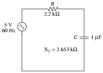
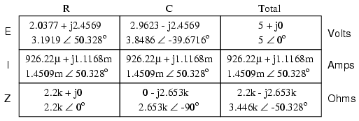
Analyzing circuit for 60 Hz source alone:
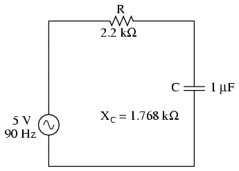
Analyzing the circuit for 90 Hz source
alone:
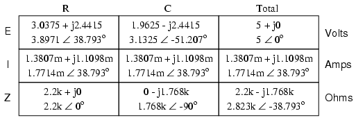
Superimposing the voltage drops across R and
C, we get:
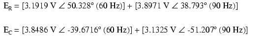
Because the two voltages across each
component are at different frequencies, we cannot
consolidate them into a single voltage figure as we could if
we were adding together two voltages of different amplitude
and/or phase angle at the same frequency. Complex number
notation give us the ability to represent waveform amplitude
(polar magnitude) and phase angle (polar angle), but not
frequency.
What we can tell from this application of
the superposition theorem is that there will be a greater 60
Hz voltage dropped across the capacitor than a 90 Hz
voltage. Just the opposite is true for the resistor's
voltage drop. This is worthy to note, especially in light of
the fact that the two source voltages are equal. It is this
kind of unequal circuit response to signals of differing
frequency that will be our specific focus in the next
chapter.
We can also apply the superposition theorem
to the analysis of a circuit powered by a non-sinusoidal
voltage, such as a square wave. If we know the Fourier
series (multiple sine/cosine wave equivalent) of that wave,
we can regard it as originating from a series-connected
string of multiple sinusoidal voltage sources at the
appropriate amplitudes, frequencies, and phase shifts.
Needless to say, this can be a laborious task for some
waveforms (an accurate square-wave Fourier Series is
considered to be expressed out to the ninth harmonic, or
five sine waves in all!), but it is possible. I mention this
not to scare you, but to inform you of the potential
complexity lurking behind seemingly simple waveforms. A
real-life circuit will respond just the same to being
powered by a square wave as being powered by an infinite
series of sine waves of odd-multiple frequencies and
diminishing amplitudes. This has been known to translate
into unexpected circuit resonances, transformer and inductor
core overheating due to eddy currents, electromagnetic noise
over broad ranges of the frequency spectrum, and the like.
Technicians and engineers need to be made aware of the
potential effects of non-sinusoidal waveforms in reactive
circuits.
Harmonics are known to manifest their
effects in the form of electromagnetic radiation as well.
Studies have been performed on the potential hazards of
using portable computers aboard passenger aircraft, citing
the fact that computers' high frequency square-wave "clock"
voltage signals are capable of generating radio waves that
could interfere with the operation of the aircraft's
electronic navigation equipment. It's bad enough that
typical microprocessor clock signal frequencies are within
the range of aircraft radio frequency bands, but worse yet
is the fact that the harmonic multiples of those fundamental
frequencies span an even larger range, due to the fact that
clock signal voltages are square-wave in shape and not
sine-wave.
Electromagnetic "emissions" of this nature
can be a problem in industrial applications, too, with
harmonics abounding in very large quantities due to
(nonlinear) electronic control of motor and electric furnace
power. The fundamental power line frequency may only be 60
Hz, but those harmonic frequency multiples theoretically
extend into infinitely high frequency ranges. Low frequency
power line voltage and current doesn't radiate into space
very well as electromagnetic energy, but high frequencies
do.
Also, capacitive and inductive "coupling"
caused by close-proximity conductors is usually more severe
at high frequencies. Signal wiring nearby power wiring will
tend to "pick up" harmonic interference from the power
wiring to a far greater extent than pure sine-wave
interference. This problem can manifest itself in industry
when old motor controls are replaced with new, solid-state
electronic motor controls providing greater energy
efficiency. Suddenly there may be weird electrical noise
being impressed upon signal wiring that never used to be
there, because the old controls never generated harmonics,
and those high-frequency harmonic voltages and currents tend
to inductively and capacitively "couple" better to nearby
conductors than any 60 Hz signals from the old controls used
to.
-
REVIEW:
-
Any regular (repeating), non-sinusoidal
waveform is equivalent to a particular series of
sine/cosine waves of different frequencies, phases, and
amplitudes, plus a DC offset voltage if necessary. The
mathematical process for determining the sinusoidal
waveform equivalent for any waveform is called Fourier
analysis.
-
Multiple-frequency voltage sources can be
simulated for analysis by connecting several
single-frequency voltage sources in series. Analysis of
voltages and currents is accomplished by using the
superposition theorem. NOTE: superimposed voltages and
currents of different frequencies cannot be added
together in complex number form, since complex numbers
only account for amplitude and phase shift, not frequency!
-
Harmonics can cause problems by impressing
unwanted ("noise") voltage signals upon nearby circuits.
These unwanted signals may come by way of capacitive
coupling, inductive coupling, electromagnetic radiation,
or a combination thereof.
|
