Musical keyboard as a signal
generator
PARTS AND MATERIALS
-
Electronic "keyboard" (musical)
-
"Mono" (not stereo) headphone-type plug
-
Impedance matching transformer (1k Ω to 8
Ω ratio; Radio Shack catalog # 273-1380)
-
10 kΩ resistor
In this experiment, you'll learn how to use
an electronic musical keyboard as a source of
variable-frequency AC voltage signals. You need not purchase
an expensive keyboard for this -- but one with at least a
few dozen "voice" selections (piano, flute, harp, etc.)
would be good. The "mono" plug will be plugged into the
headphone jack of the musical keyboard, so get a plug that's
the correct size for the keyboard.
The "impedance matching transformer" is a
small-size transformer easily obtained from an electronics
supply store. One may be scavenged from a small, junk radio:
it connects between the speaker and the circuit board
(amplifier), so is easily identifiable by location. The
primary winding is rated in ohms of impedance (1000 Ω), and
is usually center-tapped. The secondary winding is 8 Ω and
not center-tapped. These impedance figures are not the same
as DC resistance, so don't expect to read 1000 Ω and 8 Ω
with your ohmmeter -- however, the 1000 Ω winding will read
more resistance than the 8 Ω winding, because it has
more turns.
If such a transformer cannot be obtained for
the experiment, a regular 120V/6V step-down power
transformer works fairly well, too.
CROSS-REFERENCES
Lessons In Electric Circuits, Volume
2, chapter 1: "Basic AC Theory"
Lessons In Electric Circuits, Volume
2, chapter 7: "Mixed-Frequency AC Signals"
LEARNING OBJECTIVES
-
Difference between amplitude and frequency
-
Measuring AC voltage, current with a meter
-
Transformer operation, step-up
SCHEMATIC DIAGRAM
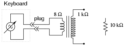
ILLUSTRATION
INSTRUCTIONS
Normally, a student of electronics in a
school would have access to a device called a signal
generator, or function generator, used to make
variable-frequency voltage waveforms to power AC circuits.
An inexpensive electronic keyboard is a cheaper alternative
to a regular signal generator, and provides features that
most signal generators cannot match, such as producing
mixed-frequency waves.
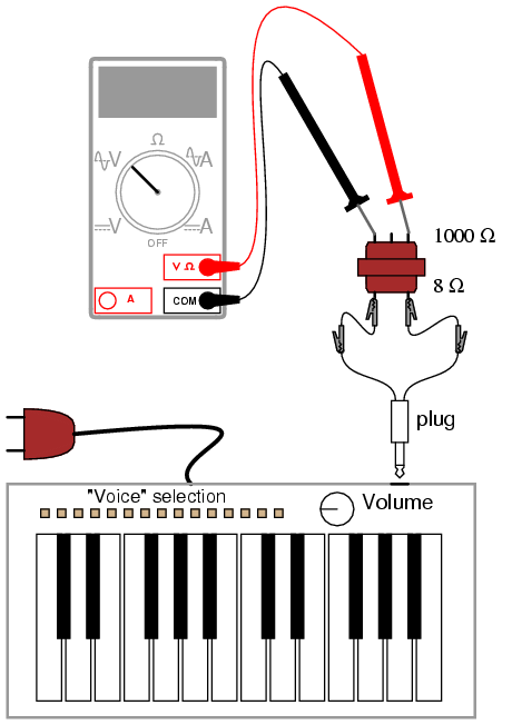
To "tap in" to the AC voltage produced by
the keyboard, you'll need to insert a plug into the
headphone jack (sometimes just labeled "phone" on the
keyboard) complete with two wires for connection to circuits
of your own design. When you insert the plug into the jack,
the normal speaker built in to the keyboard will be
disconnected (assuming the keyboard is equipped with one),
and the signal that used to power that speaker will be
available at the plug wires. In this particular experiment,
I recommend using the keyboard to power the 8 Ω side of an
audio "output" transformer to step up voltage to a higher
level. If using a power transformer instead of an audio
output transformer, connect the keyboard to the low-voltage
winding so that it operates as a step-up device. Keyboards
produce very low voltage signals, so there is no shock
hazard in this experiment.
Using an inexpensive Yamaha keyboard, I have
found that the "panflute" voice setting produces the truest
sine-wave waveform. This waveform, or something close to it
(flute, for example), is recommended to start experimenting
with since it is relatively free of harmonics (many
waveforms mixed together, of integer-multiple frequency).
Being composed of just one frequency, it is a less complex
waveform for your multimeter to measure. Make sure the
keyboard is set to a mode where the note will be sustained
as any key is held down -- otherwise, the amplitude
(voltage) of the waveform will be constantly changing (high
when the key is first pressed, then decaying rapidly to
zero).
Using an AC voltmeter, read the voltage
direct from the headphone plug. Then, read the voltage as
stepped up by the transformer, noting the step ratio. If
your multimeter has a "frequency" function, use it to
measure the frequency of the waveform produced by the
keyboard. Try different notes on the keyboard and record
their frequencies. Do you notice a pattern in frequency as
you activate different notes, especially keys that are
similar to each other (notice the 12-key black-and-white
pattern repeated on the keyboard from left to right)? If you
don't mind making marks on your keyboard, write the
frequencies in Hertz in black ink on the white keys, near
the tops where fingers are less likely to rub the numbers
off.
Ideally, there should be no change in signal
amplitude (voltage) as different frequencies (notes on the
keyboard) are tried. If you adjust the volume up and down,
you should discover that changes in amplitude should have
little or no impact on frequency measurement. Amplitude and
frequency are two completely independent aspects of an AC
signal.
Try connecting the keyboard output to a 10
kΩ load resistance (through the headphone plug), and measure
AC current with your multimeter. If your multimeter has a
frequency function, you can measure the frequency of this
current as well. It should be the same as for the voltage
for any given note (keyboard key). |
