Sensitive audio detector
PARTS AND MATERIALS
-
High-quality "closed-cup" audio headphones
-
Headphone jack: female receptacle for
headphone plug (Radio Shack catalog # 274-312)
-
Small step-down power transformer (Radio
Shack catalog # 273-1365 or equivalent, using the 6-volt
secondary winding tap)
-
Two 1N4001 rectifying diodes (Radio Shack
catalog # 276-1101)
-
1 kΩ resistor
-
100 kΩ potentiometer (Radio Shack catalog
# 271-092)
-
Two "banana" jack style binding posts, or
other terminal hardware, for connection to potentiometer
circuit (Radio Shack catalog # 274-662 or equivalent)
-
Plastic or metal mounting box
Regarding the headphones, the higher the
"sensitivity" rating in decibels (dB), the better, but
listening is believing: if you're serious about building a
detector with maximum sensitivity for small electrical
signals, you should try a few different headphone models at
a high-quality audio store and "listen" for which ones
produce an audible sound for the lowest volume
setting on a radio or CD player. Beware, as you could spend
hundreds of dollars on a pair of headphones to get the
absolute best sensitivity! Take heart, though: I've used an
old pair of Radio Shack "Realistic" brand headphones
with perfectly adequate results, so you don't need to buy
the best.
Normally, the transformer used in this type
of application (audio speaker impedance matching) is called
an "audio transformer," with its primary and secondary
windings represented by impedance values (1000 Ω : 8 Ω)
instead of voltages. An audio transformer will work, but
I've found small step-down power transformers of 120/6 volt
ratio to be perfectly adequate for the task, cheaper
(especially when taken from an old thrift-store alarm clock
radio), and far more rugged.
The tolerance (precision) rating for the 1
kΩ resistor is irrelevant. The 100 kΩ potentiometer is a
recommended option for incorporation into this project, as
it gives the user control over the loudness for any given
signal. Even though an audio-taper potentiometer
would be appropriate for this application, it is not
necessary. A linear-taper potentiometer works quite
well.
CROSS-REFERENCES
Lessons In Electric Circuits, Volume
1, chapter 8: "DC Metering Circuits"
Lessons In Electric Circuits, Volume
2, chapter 9: "Transformers"
Lessons In Electric Circuits, Volume
2, chapter 12: "AC Metering Circuits"
LEARNING OBJECTIVES
-
Soldering practice
-
Use of a transformer for impedance
matching
-
Detection of extremely small electrical
signals
-
Using diodes to "clip" voltage at some
maximum level
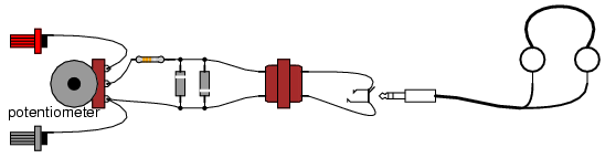
SCHEMATIC DIAGRAM
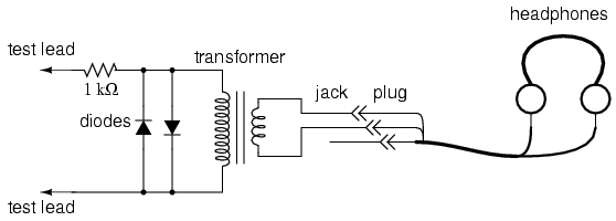
ILLUSTRATION
INSTRUCTIONS
This experiment is identical in construction
to the "Sensitive Voltage Detector" described in the DC
experiments chapter. If you've already built this detector,
you may skip this experiment.
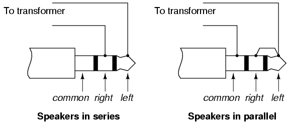
The headphones, most likely being stereo
units (separate left and right speakers) will have a
three-contact plug. You will be connecting to only two of
those three contact points. If you only have a "mono"
headphone set with a two-contact plug, just connect to those
two contact points. You may either connect the two stereo
speakers in series or in parallel. I've found the series
connection to work best, that is, to produce the most sound
from a small signal:
Solder all wire connections well. This
detector system is extremely sensitive, and any loose wire
connections in the circuit will add unwanted noise to the
sounds produced by the measured voltage signal. The two
diodes connected in parallel with the transformer's primary
winding, along with the series-connected 1 kΩ resistor, work
together to "clip" the input voltage to a maximum of about
0.7 volts. This does one thing and one thing only: limit the
amount of sound the headphones can produce. The system will
work without the diodes and resistor in place, but there
will be no limit to sound volume in the circuit, and the
resulting sound caused by accidently connecting the test
leads across a substantial voltage source (like a battery)
can be deafening!
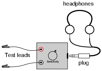
Binding posts provide points of connection
for a pair of test probes with banana-style plugs, once the
detector components are mounted inside a box. You may use
ordinary multimeter probes, or make your own probes with
alligator clips at the ends for secure connection to a
circuit.
Detectors are intended to be used for
balancing bridge measurement circuits, potentiometric
(null-balance) voltmeter circuits, and detect extremely
low-amplitude AC ("alternating current") signals in the
audio frequency range. It is a valuable piece of test
equipment, especially for the low-budget experimenter
without an oscilloscope. It is also valuable in that it
allows you to use a different bodily sense in interpreting
the behavior of a circuit.
For connection across any non-trivial source
of voltage (1 volt and greater), the detector's extremely
high sensitivity should be attenuated. This may be
accomplished by connecting a voltage divider to the "front"
of the circuit:
SCHEMATIC DIAGRAM
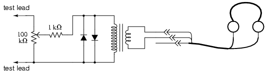
ILLUSTRATION
Adjust the 100 kΩ voltage divider
potentiometer to about mid-range when initially sensing a
voltage signal of unknown magnitude. If the sound is too
loud, turn the potentiometer down and try again. If too
soft, turn it up and try again. This detector even senses DC
and radio-frequency signals (frequencies below and above the
audio range, respectively), a "click" being heard whenever
the test leads make or break contact with the source under
test. With my cheap headphones, I've been able to detect
currents of less than 1/10 of a microamp (< 0.1 �A) DC, and
similarly low-magnitude RF signals up to 2 MHz.
A good demonstration of the detector's
sensitivity is to touch both test leads to the end of your
tongue, with the sensitivity adjustment set to maximum. The
voltage produced by metal-to-electrolyte contact (called
galvanic voltage) is very small, but enough to produce
soft "clicking" sounds every time the leads make and break
contact on the wet skin of your tongue.
Try unplugged the headphone plug from the
jack (receptacle) and similarly touching it to the end of
your tongue. You should still hear soft clicking sounds, but
they will be much smaller in amplitude. Headphone speakers
are "low impedance" devices: they require low voltage and
"high" current to deliver substantial sound power. Impedance
is a measure of opposition to any and all forms of electric
current, including alternating current (AC). Resistance, by
comparison, is a strictly measure of opposition to direct
current (DC). Like resistance, impedance is measured in the
unit of the Ohm (Ω), but it is symbolized in equations by
the capital letter "Z" rather than the capital letter "R".
We use the term "impedance" to describe the headphone's
opposition to current because it is primarily AC signals
that headphones are normally subjected to, not DC.
Most small signal sources have high internal
impedances, some much higher than the nominal 8 Ω of the
headphone speakers. This is a technical way of saying that
they are incapable of supplying substantial amounts of
current. As the Maximum Power Transfer Theorem predicts,
maximum sound power will be delivered by the headphone
speakers when their impedance is "matched" to the impedance
of the voltage source. The transformer does this. The
transformer also helps aid the detection of small DC signals
by producing inductive "kickback" every time the test lead
circuit is broken, thus "amplifying" the signal by
magnetically storing up electrical energy and suddenly
releasing it to the headphone speakers.
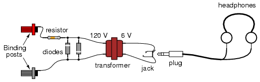
As with the low-voltage AC power supply
experiment, I recommend building this detector in a
permanent fashion (mounting all components inside of a box,
and providing nice test lead wires) so it can be easily used
in the future. Constructed as such, it might look something
like this:
 |
