Special transformers and
applications
Because transformers can step voltage and
current to different levels, and because power is
transferred equivalently between primary and secondary
windings, they can be used to "convert" the impedance of a
load to a different level. That last phrase deserves some
explanation, so let's investigate what it means.
The purpose of a load (usually) is to do
something productive with the power it dissipates. In the
case of a resistive heating element, the practical purpose
for the power dissipated is to heat something up. Loads are
engineered to safely dissipate a certain maximum amount of
power, but two loads of equal power rating are not
necessarily identical. Consider these two 1000 watt
resistive heating elements:
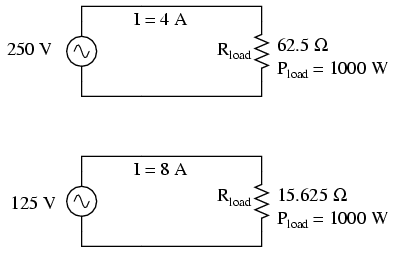
Both heaters dissipate exactly 1000 watts of
power, but they do so at different voltage and current
levels (either 250 volts and 4 amps, or 125 volts and 8
amps). Using Ohm's Law to determine the necessary resistance
of these heating elements (R=E/I), we arrive at figures of
62.5 Ω and 15.625 Ω, respectively. If these are AC loads, we
might refer to their opposition to current in terms of
impedance rather than plain resistance, although in this
case that's all they're composed of (no reactance). The 250
volt heater would be said to be a higher impedance load than
the 125 volt heater.
If we desired to operate the 250 volt heater
element directly on a 125 volt power system, we would end up
being disappointed. With 62.5 Ω of impedance (resistance),
the current would only be 2 amps (I=E/R; 125/62.5), and the
power dissipation would only be 250 watts (P=IE; 125 x 2),
or one-quarter of its rated power. The impedance of the
heater and the voltage of our source would be mismatched,
and we couldn't obtain the full rated power dissipation from
the heater.
All hope is not lost, though. With a step-up
transformer, we could operate the 250 volt heater element on
the 125 volt power system like this:
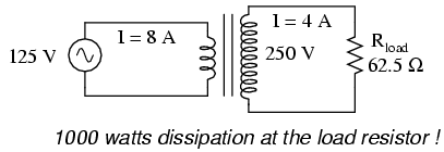
The ratio of the transformer's windings
provides the voltage step-up and current step-down we
need for the otherwise mismatched load to operate properly
on this system. Take a close look at the primary circuit
figures: 125 volts at 8 amps. As far as the power supply
"knows," it's powering a 15.625 Ω (R=E/I) load at 125 volts,
not a 62.5 Ω load! The voltage and current figures for the
primary winding are indicative of 15.625 Ω load impedance,
not the actual 62.5 Ω of the load itself. In other words,
not only has our step-up transformer transformed voltage and
current, but it has transformed impedance as well.
The transformation ratio of impedance is the
square of the voltage/current transformation ratio, the same
as the winding inductance ratio:
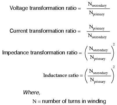
This concurs with our example of the 2:1
step-up transformer and the impedance ratio of 62.5 Ω to
15.625 Ω (a 4:1 ratio, which is 2:1 squared). Impedance
transformation is a highly useful ability of transformers,
for it allows a load to dissipate its full rated power even
if the power system is not at the proper voltage to directly
do so.
Recall from our study of network analysis
the Maximum Power Transfer Theorem, which states that
the maximum amount of power will be dissipated by a load
resistance when that load resistance is equal to the
Thevenin/Norton resistance of the network supplying the
power. Substitute the word "impedance" for "resistance" in
that definition and you have the AC version of that Theorem.
If we're trying to obtain theoretical maximum power
dissipation from a load, we must be able to properly match
the load impedance and source (Thevenin/Norton) impedance
together. This is generally more of a concern in specialized
electric circuits such as radio transmitter/antenna and
audio amplifier/speaker systems. Let's take an audio
amplifier system and see how it works:
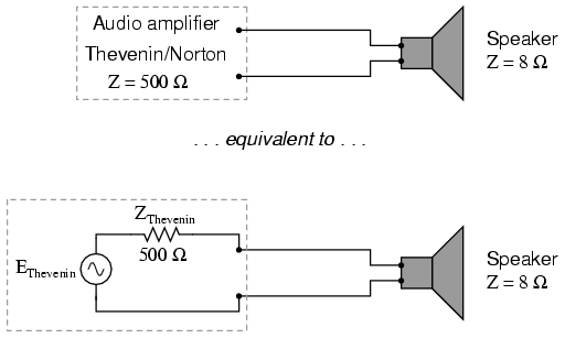
With an internal impedance of 500 Ω, the
amplifier can only deliver full power to a load (speaker)
also having 500 Ω of impedance. Such a load would drop
higher voltage and draw less current than an 8 Ω speaker
dissipating the same amount of power. If an 8 Ω speaker were
connected directly to the 500 Ω amplifier as shown, the
impedance mismatch would result in very poor (low peak
power) performance. Additionally, the amplifier would tend
to dissipate more than its fair share of power in the form
of heat trying to drive the low impedance speaker.
To make this system work better, we can use
a transformer to match these mismatched impedances. Since
we're going from a high impedance (high voltage, low
current) supply to a low impedance (low voltage, high
current) load, we'll need to use a step-down transformer:
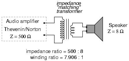
To obtain an impedance transformation ratio
of 500:8, we would need a winding ratio equal to the square
root of 500:8 (the square root of 62.5:1, or 7.906:1). With
such a transformer in place, the speaker will load the
amplifier to just the right degree, drawing power at the
correct voltage and current levels to satisfy the Maximum
Power Transfer Theorem and make for the most efficient power
delivery to the load. The use of a transformer in this
capacity is called impedance matching.
Anyone who has ridden a multi-speed bicycle
can intuitively understand the principle of impedance
matching. A human's legs will produce maximum power when
spinning the bicycle crank at a particular speed (about 60
to 90 revolution per minute). Above or below that rotational
speed, human leg muscles are less efficient at generating
power. The purpose of the bicycle's "gears" is to
impedance-match the rider's legs to the riding conditions so
that they always spin the crank at the optimum speed.
If the rider attempts to start moving while
the bicycle is shifted into its "top" gear, he or she will
find it very difficult to get moving. Is it because the
rider is weak? No, it's because the high step-up ratio of
the bicycle's chain and sprockets in that top gear presents
a mismatch between the conditions (lots of inertia to
overcome) and their legs (needing to spin at 60-90 RPM for
maximum power output). On the other hand, selecting a gear
that is too low will enable the rider to get moving
immediately, but limit the top speed they will be able to
attain. Again, is the lack of speed an indication of
weakness in the bicyclist's legs? No, it's because the lower
speed ratio of the selected gear creates another type of
mismatch between the conditions (low load) and the rider's
legs (losing power if spinning faster than 90 RPM). It is
much the same with electric power sources and loads: there
must be an impedance match for maximum system efficiency. In
AC circuits, transformers perform the same matching function
as the sprockets and chain ("gears") on a bicycle to match
otherwise mismatched sources and loads.
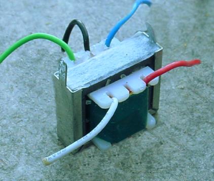
Impedance matching transformers are not
fundamentally different from any other type of transformer
in construction or appearance. A small impedance-matching
transformer (about two centimeters in width) for
audio-frequency applications is shown in the following
photograph:
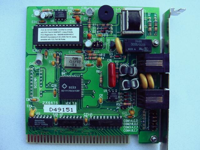
Another impedance-matching transformer can
be seen on this printed circuit board, in the upper right
corner, to the immediate left of resistors R2 and
R1. It is labeled "T1":
Transformers can also be used in electrical
instrumentation systems. Due to transformers' ability to
step up or step down voltage and current, and the electrical
isolation they provide, they can serve as a way of
connecting electrical instrumentation to high-voltage, high
current power systems. Suppose we wanted to accurately
measure the voltage of a 13.8 kV power system (a very common
power distribution voltage in American industry):
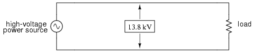
Designing, installing, and maintaining a
voltmeter capable of directly measuring 13,800 volts AC
would be no easy task. The safety hazard alone of bringing
13.8 kV conductors into an instrument panel would be severe,
not to mention the design of the voltmeter itself. However,
by using a precision step-down transformer, we can reduce
the 13.8 kV down to a safe level of voltage at a constant
ratio, and isolate it from the instrument connections,
adding an additional level of safety to the metering system:
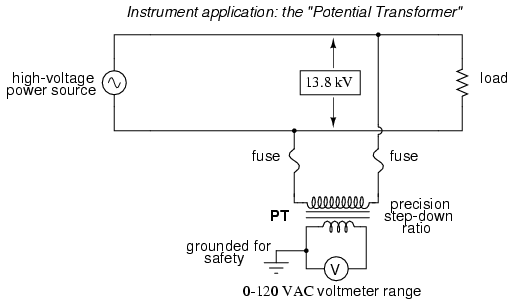
Now the voltmeter reads a precise fraction,
or ratio, of the actual system voltage, its scale set to
read as though it were measuring the voltage directly. The
transformer keeps the instrument voltage at a safe level and
electrically isolates it from the power system, so there is
no direct connection between the power lines and the
instrument or instrument wiring. When used in this capacity,
the transformer is called a Potential Transformer, or
simply PT.
Potential transformers are designed to
provide as accurate a voltage step-down ratio as possible.
To aid in precise voltage regulation, loading is kept to a
minimum: the voltmeter is made to have high input impedance
so as to draw as little current from the PT as possible. As
you can see, a fuse has been connected in series with the
PTs primary winding, for safety and ease of disconnecting
the PT from the circuit.
A standard secondary voltage for a PT is 120
volts AC, for full-rated power line voltage. The standard
voltmeter range to accompany a PT is 150 volts, full-scale.
PTs with custom winding ratios can be manufactured to suit
any application. This lends itself well to industry
standardization of the actual voltmeter instruments
themselves, since the PT will be sized to step the system
voltage down to this standard instrument level.
Following the same line of thinking, we can
use a transformer to step down current through a power line
so that we are able to safely and easily measure high system
currents with inexpensive ammeters. Of course, such a
transformer would be connected in series with the power
line, like this:

Note that while the PT is a step-down
device, the Current Transformer (or CT) is a
step-up device (with respect to voltage), which is what is
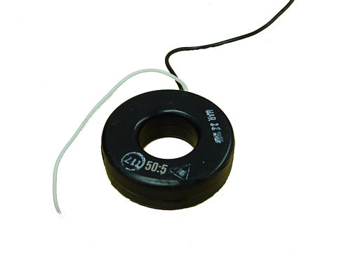
needed to step down the power line current. Quite
often, CTs are built as donut-shaped devices through which
the power line conductor is run, the power line itself
acting as a single-turn primary winding:
Some CTs are made to hinge open, allowing
insertion around a power conductor without disturbing the
conductor at all. The industry standard secondary current
for a CT is a range of 0 to 5 amps AC. Like PTs, CTs can be
made with custom winding ratios to fit almost any
application. Because their "full load" secondary current is
5 amps, CT ratios are usually described in terms of
full-load primary amps to 5 amps, like this:
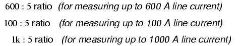
The "donut" CT shown in the photograph has a
ratio of 50:5. That is, when the conductor through the
center of the torus is carrying 50 amps of current (AC),
there will be 5 amps of current induced in the CT's winding.
Because CTs are designed to be powering
ammeters, which are low-impedance loads, and they are wound
as voltage step-up transformers, they should never, ever
be operated with an open-circuited secondary winding.
Failure to heed this warning will result in the CT producing
extremely high secondary voltages, dangerous to equipment
and personnel alike. To facilitate maintenance of ammeter
instrumentation, short-circuiting switches are often
installed in parallel with the CT's secondary winding, to be
closed whenever the ammeter is removed for service:
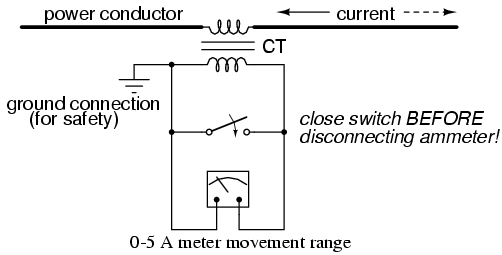
Though it may seem strange to
intentionally short-circuit a power system component, it
is perfectly proper and quite necessary when working with
current transformers.
Another kind of special transformer, seen
often in radio-frequency circuits, is the air core
transformer. True to its name, an air core transformer has
its windings wrapped around a nonmagnetic form, usually a
hollow tube of some material. The degree of coupling (mutual
inductance) between windings in such a transformer is many
times less than that of an equivalent iron-core transformer,
but the undesirable characteristics of a ferromagnetic core
(eddy current losses, hysteresis, saturation, etc.) are
completely eliminated. It is in high-frequency applications
that these effects of iron cores are most problematic.
One notable example of air-core transformer
is the Tesla Coil, named after the Serbian electrical
genius Nikola Tesla, who was also the inventor of the
rotating magnetic field AC motor, polyphase AC power
systems, and many elements of radio technology. The Tesla
Coil is a resonant, high-frequency step-up transformer used
to produce extremely high voltages. One of Tesla's dreams
was to employ his coil technology to distribute electric
power without the need for wires, simply broadcasting it in
the form of radio waves which could be received and
conducted to loads by means of antennas. The basic schematic
for a Tesla Coil looks like this:

The capacitor, in conjunction with the
transformer's primary winding, forms a tank circuit. The
secondary winding is wound in close proximity to the
primary, usually around the same nonmagnetic form. Several
options exist for "exciting" the primary circuit, the
simplest being a high-voltage, low-frequency AC source and
spark gap:
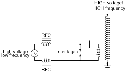
The purpose of the high-voltage,
low-frequency AC power source is to "charge" the primary
tank circuit. When the spark gap fires, its low impedance
acts to complete the capacitor/primary coil tank circuit,
allowing it to oscillate at its resonant frequency. The "RFC"
inductors are "Radio Frequency Chokes," which act as high
impedances to prevent the AC source from interfering with
the oscillating tank circuit.
The secondary side of the Tesla coil
transformer is also a tank circuit, relying on the parasitic
(stray) capacitance existing between the discharge terminal
and earth ground to complement the secondary winding's
inductance. For optimum operation, this secondary tank
circuit is tuned to the same resonant frequency as the
primary circuit, with energy exchanged not only between
capacitors and inductors during resonant oscillation, but
also back-and-forth between primary and secondary windings.
The visual results are spectacular:
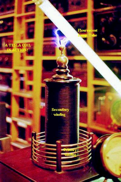
Tesla Coils find application primarily as
novelty devices, showing up in high school science fairs,
basement workshops, and the occasional low budget
science-fiction movie.
It should be noted that Tesla coils can be
extremely dangerous devices. Burns caused by radio-frequency
("RF") current, like all electrical burns, can be very deep,
unlike skin burns caused by contact with hot objects or
flames. Although the high-frequency discharge of a Tesla
coil has the curious property of being beyond the "shock
perception" frequency of the human nervous system, this does
not mean Tesla coils cannot hurt or even kill you! I
strongly advise seeking the assistance of an experienced
Tesla coil experimenter if you would embark on building one
yourself.
So far, we've explored the transformer as a
device for converting different levels of voltage, current,
and even impedance from one circuit to another. Now we'll
take a look at it as a completely different kind of device:
one that allows a small electrical signal to exert
control over a much larger quantity of electrical power.
In this mode, a transformer acts as an amplifier.
The device I'm referring to is called a
saturable-core reactor, or simply saturable reactor.
Actually, it is not really a transformer at all, but rather
a special kind of inductor whose inductance can be varied by
the application of a DC current through a second winding
wound around the same iron core. Like the ferroresonant
transformer, the saturable reactor relies on the principle
of magnetic saturation. When a material such as iron is
completely saturated (that is, all its magnetic domains are
lined up with the applied magnetizing force), additional
increases in current through the magnetizing winding will
not result in further increases of magnetic flux.
Now, inductance is the measure of how well
an inductor opposes changes in current by developing a
voltage in an opposing direction. The ability of an inductor
to generate this opposing voltage is directly connected with
the change in magnetic flux inside the inductor resulting
from the change in current, and the number of winding turns
in the inductor. If an inductor has a saturated core, no
further magnetic flux will result from further increases in
current, and so there will be no voltage induced in
opposition to the change in current. In other words, an
inductor loses its inductance (ability to oppose changes in
current) when its core becomes magnetically saturated.
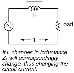
If an inductor's inductance changes, then
its reactance (and impedance) to AC current changes as well.
In a circuit with a constant voltage source, this will
result in a change in current:
A saturable reactor capitalizes on this
effect by forcing the core into a state of saturation with a
strong magnetic field generated by current through another
winding. The reactor's "power" winding is the one carrying
the AC load current, and the "control" winding is one
carrying a DC current strong enough to drive the core into
saturation:

The strange-looking transformer symbol shown
in the above schematic represents a saturable-core reactor,
the upper winding being the DC control winding and the lower
being the "power" winding through which the controlled AC
current goes. Increased DC control current produces more
magnetic flux in the reactor core, driving it closer to a
condition of saturation, thus decreasing the power winding's
inductance, decreasing its impedance, and increasing current
to the load. Thus, the DC control current is able to exert
control over the AC current delivered to the load.
The circuit shown would work, but it would
not work very well. The first problem is the natural
transformer action of the saturable reactor: AC current
through the power winding will induce a voltage in the
control winding, which may cause trouble for the DC power
source. Also, saturable reactors tend to regulate AC power
only in one direction: in one half of the AC cycle, the
mmf's from both windings add; in the other half, they
subtract. Thus, the core will have more flux in it during
one half of the AC cycle than the other, and will saturate
first in that cycle half, passing load current more easily
in one direction than the other. Fortunately, both problems
can be overcome with a little ingenuity:
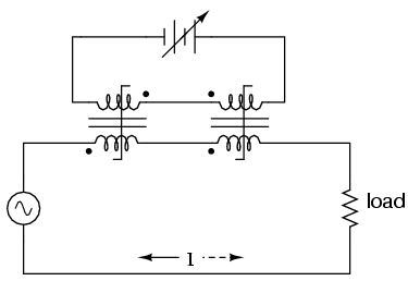
Notice the placement of the phasing dots on
the two reactors: the power windings are "in phase" while
the control windings are "out of phase." If both reactors
are identical, any voltage induced in the control windings
by load current through the power windings will cancel out
to zero at the battery terminals, thus eliminating the first
problem mentioned. Furthermore, since the DC control current
through both reactors produces magnetic fluxes in different
directions through the reactor cores, one reactor will
saturate more in one cycle of the AC power while the other
reactor will saturate more in the other, thus equalizing the
control action through each half-cycle so that the AC power
is "throttled" symmetrically. This phasing of control
windings can be accomplished with two separate reactors as
shown, or in a single reactor design with intelligent layout
of the windings and core.
Saturable reactor technology has even been
miniaturized to the circuit-board level in compact packages
more generally known as magnetic amplifiers. I
personally find this to be fascinating: the effect of
amplification (one electrical signal controlling another),
normally requiring the use of physically fragile vacuum
tubes or electrically "fragile" semiconductor devices, can
be realized in a device both physically and electrically
rugged. Magnetic amplifiers do have disadvantages over their
more fragile counterparts, namely size, weight,
nonlinearity, and bandwidth (frequency response), but their
utter simplicity still commands a certain degree of
appreciation, if not practical application.
Saturable-core reactors are less commonly
known as "saturable-core inductors" or transductors.
-
REVIEW:
-
Transformers can be used to transform
impedance as well as voltage and current. When this is
done to improve power transfer to a load, it is called
impedance matching.
-
A Potential Transformer (PT) is a
special instrument transformer designed to provide a
precise voltage step-down ratio for voltmeters measuring
high power system voltages.
-
A Current Transformer (CT) is
another special instrument transformer designed to step
down the current through a power line to a safe level for
an ammeter to measure.
-
An air-core transformer is one
lacking a ferromagnetic core.
-
A Tesla Coil is a resonant,
air-core, step-up transformer designed to produce very
high AC voltages at high frequency.
-
A saturable reactor is a special
type of inductor, the inductance of which can be
controlled by the DC current through a second winding
around the same core. With enough DC current, the magnetic
core can be saturated, decreasing the inductance of the
power winding in a controlled fashion.
|
