Step-up and step-down transformers
So far, we've observed simulations of
transformers where the primary and secondary windings were
of identical inductance, giving approximately equal voltage
and current levels in both circuits. Equality of voltage and
current between the primary and secondary sides of a
transformer, however, is not the norm for all transformers.
If the inductances of the two windings are not equal,
something interesting happens:
transformer
v1 1 0 ac 10 sin
rbogus1 1 2 1e-12
rbogus2 5 0 9e12
l1 2 0 10000
l2 3 5 100
k l1 l2 0.999
vi1 3 4 ac 0
rload 4 5 1k
.ac lin 1 60 60
.print ac v(2,0) i(v1)
.print ac v(3,5) i(vi1)
.end
freq          v(2)        i(v1)
6.000E+01     1.000E+01   9.975E-05    Primary winding
freq          v(3,5)      i(vi1)
6.000E+01     9.962E-01   9.962E-04    Secondary winding
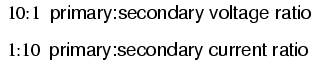
Notice how the secondary voltage is
approximately ten times less than the primary voltage
(0.9962 volts compared to 10 volts), while the secondary
current is approximately ten times greater (0.9962 mA
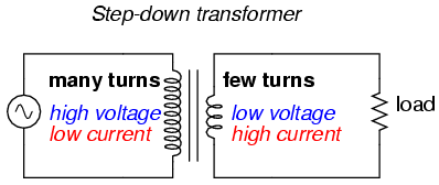
compared to 0.09975 mA). What we have here is a device that
steps voltage down by a factor of ten and current
up by a factor of ten:
This is a very useful device, indeed. With
it, we can easily multiply or divide voltage and current in
AC circuits. Indeed, the transformer has made long-distance
transmission of electric power a practical reality, as AC
voltage can be "stepped up" and current "stepped down" for
reduced wire resistance power losses along power lines
connecting generating stations with loads. At either end
(both the generator and at the loads), voltage levels are
reduced by transformers for safer operation and less
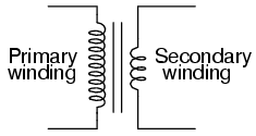
expensive equipment. A transformer that increases voltage
from primary to secondary (more secondary winding turns than
primary winding turns) is called a step-up
transformer. Conversely, a transformer designed to do just
the opposite is called a step-down transformer.
Let's re-examine a photograph shown in the
previous section:
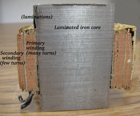
This is a step-down transformer, as
evidenced by the high turn count of the primary winding and
the low turn count of the secondary. As a step-down unit,
this transformer converts high-voltage, low-current power
into low-voltage, high-current power. The larger-gauge wire
used in the secondary winding is necessary due to the
increase in current. The primary winding, which doesn't have
to conduct as much current, may be made of smaller-gauge
wire.
In case you were wondering, it is
possible to operate either of these transformer types
backwards (powering the secondary winding with an AC source
and letting the primary winding power a load) to perform the
opposite function: a step-up can function as a step-down and
visa-versa. However, as we saw in the first section of this
chapter, efficient operation of a transformer requires that
the individual winding inductances be engineered for
specific operating ranges of voltage and current, so if a
transformer is to be used "backwards" like this it must be
employed within the original design parameters of voltage
and current for each winding, lest it prove to be
inefficient (or lest it be damaged by excessive
voltage or current!).
Transformers are often constructed in such a
way that it is not obvious which wires lead to the primary
winding and which lead to the secondary. One convention used
in the electric power industry to help alleviate confusion
is the use of "H" designations for the higher-voltage
winding (the primary winding in a step-down unit; the
secondary winding in a step-up) and "X" designations for the
lower-voltage winding. Therefore, a simple power transformer
will have wires labeled "H1", "H2", "X1",
and "X2". There is usually significance to the
numbering of the wires (H1 versus H2,
etc.), which we'll explore a little later in this chapter.
The fact that voltage and current get
"stepped" in opposite directions (one up, the other down)
makes perfect sense when you recall that power is equal to
voltage times current, and realize that transformers cannot
produce power, only convert it. Any device that could
output more power than it took in would violate the Law
of Energy Conservation in physics, namely that energy
cannot be created or destroyed, only converted. As with the
first transformer example we looked at, power transfer
efficiency is very good from the primary to the secondary
sides of the device.
The practical significance of this is made
more apparent when an alternative is considered: before the
advent of efficient transformers, voltage/current level
conversion could only be achieved through the use of
motor/generator sets. A drawing of a motor/generator set
reveals the basic principle involved:
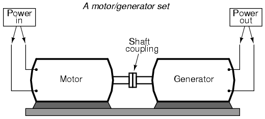
In such a machine, a motor is mechanically
coupled to a generator, the generator designed to produce
the desired levels of voltage and current at the rotating
speed of the motor. While both motors and generators are
fairly efficient devices, the use of both in this fashion
compounds their inefficiencies so that the overall
efficiency is in the range of 90% or less. Furthermore,
because motor/generator sets obviously require moving parts,
mechanical wear and balance are factors influencing both
service life and performance. Transformers, on the other
hand, are able to convert levels of AC voltage and current
at very high efficiencies with no moving parts, making
possible the widespread distribution and use of electric
power we take for granted.
In all fairness it should be noted that
motor/generator sets have not necessarily been obsoleted by
transformers for all applications. While transformers
are clearly superior over motor/generator sets for AC
voltage and current level conversion, they cannot convert
one frequency of AC power to another, or (by themselves)
convert DC to AC or visa-versa. Motor/generator sets can do
all these things with relative simplicity, albeit with the
limitations of efficiency and mechanical factors already
described. Motor/generator sets also have the unique
property of kinetic energy storage: that is, if the motor's
power supply is momentarily interrupted for any reason, its
angular momentum (the inertia of that rotating mass) will
maintain rotation of the generator for a short duration,
thus isolating any loads powered by the generator from
"glitches" in the main power system.
Looking closely at the numbers in the SPICE
analysis, we should see a correspondence between the
transformer's ratio and the two inductances. Notice how the
primary inductor (l1) has 100 times more inductance than the
secondary inductor (10000 H versus 100 H), and that the
measured voltage step-down ratio was 10 to 1. The winding
with more inductance will have higher voltage and less
current than the other. Since the two inductors are wound
around the same core material in the transformer (for the
most efficient magnetic coupling between the two), the
parameters affecting inductance for the two coils are equal
except for the number of turns in each coil. If we take
another look at our inductance formula, we see that
inductance is proportional to the square of the
number of coil turns:
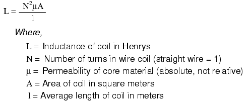
So, it should be apparent that our two
inductors in the last SPICE transformer example circuit --
with inductance ratios of 100:1 -- should have coil turn
ratios of 10:1, because 10 squared equals 100. This works
out to be the same ratio we found between primary and
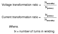
secondary voltages and currents (10:1), so we can say as a
rule that the voltage and current transformation ratio is
equal to the ratio of winding turns between primary and
secondary.
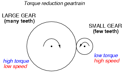
The step-up/step-down effect of coil turn
ratios in a transformer is analogous to gear tooth ratios in
mechanical gear systems, transforming values of speed and
torque in much the same way:
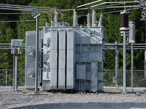
Step-up and step-down transformers for power
distribution purposes can be gigantic in proportion to the
power transformers previously shown, some units standing as
tall as a home. The following photograph shows a substation
transformer standing about twelve feet tall:
-
REVIEW:
-
Transformers "step up" or "step down"
voltage according to the ratios of primary to secondary
wire turns.
-
-
A transformer designed to increase voltage
from primary to secondary is called a step-up
transformer. A transformer designed to reduce voltage from
primary to secondary is called a step-down
transformer.
-
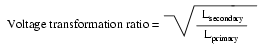
The transformation ratio of a transformer
will be equal to the square root of its primary to
secondary inductance (L) ratio.
-
|
