Voltage regulation
As we saw in a few SPICE analyses earlier in
this chapter, the output voltage of a transformer varies
some with varying load resistances, even with a constant
voltage input. The degree of variance is affected by the
primary and secondary winding inductances, among other
factors, not the least of which includes winding resistance
and the degree of mutual inductance (magnetic coupling)
between the primary and secondary windings. For power
transformer applications, where the transformer is seen by
the load (ideally) as a constant source of voltage, it is
good to have the secondary voltage vary as little as
possible for wide variances in load current.
The measure of how well a power transformer
maintains constant secondary voltage over a range of load
currents is called the transformer's voltage regulation.
It can be calculated from the following formula:
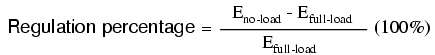
"Full-load" means the point at which the
transformer is operating at maximum permissible secondary
current. This operating point will be determined primarily
by the winding wire size (ampacity) and the method of
transformer cooling. Taking our first SPICE transformer
simulation as an example, let's compare the output voltage
with a 1 kΩ load versus a 200 Ω load (assuming that the 200
Ω load will be our "full load" condition). Recall if you
will that our constant primary voltage was 10.00 volts AC:
freq          v(3,5)      i(vi1)
6.000E+01     9.962E+00   9.962E-03    Output with 1k ohm load
freq          v(3,5)      i(vi1)
6.000E+01     9.348E+00   4.674E-02    Output with 200 ohm load
Notice how the output voltage decreases as
the load gets heavier (more current). Now let's take that
same transformer circuit and place a load resistance of
extremely high magnitude across the secondary winding to
simulate a "no-load" condition:
transformer
v1 1 0 ac 10 sin
rbogus1 1 2 1e-12
rbogus2 5 0 9e12
l1 2 0 100
l2 3 5 100
k l1 l2 0.999
vi1 3 4 ac 0
rload 4 5 9e12
.ac lin 1 60 60
.print ac v(2,0) i(v1)
.print ac v(3,5) i(vi1)
.end
freq          v(2)        i(v1)
6.000E+01     1.000E+01   2.653E-04
freq          v(3,5)      i(vi1)
6.000E+01     9.990E+00   1.110E-12   Output with (almost) no load
So, we see that our output (secondary)
voltage spans a range of 9.990 volts at (virtually) no load
and 9.348 volts at the point we decided to call "full load."
Calculating voltage regulation with these figures, we get:
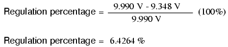
Incidentally, this would be considered
rather poor (or "loose") regulation for a power transformer.
Powering a simple resistive load like this, a good power
transformer should exhibit a regulation percentage of less
than 3%. Inductive loads tend to create a condition of worse
voltage regulation, so this analysis with purely resistive
loads was a "best-case" condition.
There are some applications, however, where
poor regulation is actually desired. One such case is in
discharge lighting, where a step-up transformer is required
to initially generate a high voltage (necessary to "ignite"
the lamps), then the voltage is expected to drop off once
the lamp begins to draw current. This is because discharge
lamps' voltage requirements tend to be much lower after a
current has been established through the arc path. In this
case, a step-up transformer with poor voltage regulation
suffices nicely for the task of conditioning power to the
lamp.
Another application is in current control
for AC arc welders, which are nothing more than step-down
transformers supplying low-voltage, high-current power for
the welding process. A high voltage is desired to assist in
"striking" the arc (getting it started), but like the
discharge lamp, an arc doesn't require as much voltage to
sustain itself once the air has been heated to the point of
ionization. Thus, a decrease of secondary voltage under high
load current would be a good thing. Some arc welder designs
provide arc current adjustment by means of a movable iron
core in the transformer, cranked in or out of the winding
assembly by the operator. Moving the iron slug away from the
windings reduces the strength of magnetic coupling between
the windings, which diminishes no-load secondary voltage
and makes for poorer voltage regulation.
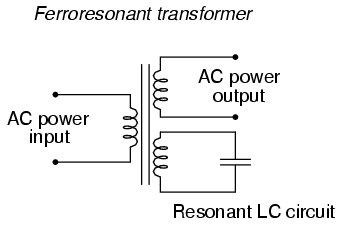
No exposition on transformer regulation
could be called complete without mention of an unusual
device called a ferroresonant transformer. "Ferroresonance"
is a phenomenon associated with the behavior of iron cores
while operating near a point of magnetic saturation (where
the core is so strongly magnetized that further increases in
winding current results in little or no increase in magnetic
flux).
While being somewhat difficult to describe
without going deep into electromagnetic theory, the
ferroresonant transformer is a power transformer engineered
to operate in a condition of persistent core saturation.
That is, its iron core is "stuffed full" of magnetic lines
of flux for a large portion of the AC cycle so that
variations in supply voltage (primary winding current) have
little effect on the core's magnetic flux density, which
means the secondary winding outputs a nearly constant
voltage despite significant variations in supply (primary
winding) voltage. Normally, core saturation in a transformer
results in distortion of the sinewave shape, and the
ferroresonant transformer is no exception. To combat this
side effect, ferroresonant transformers have an auxiliary
secondary winding paralleled with one or more capacitors,
forming a resonant circuit tuned to the power supply
frequency. This "tank circuit" serves as a filter to reject
harmonics created by the core saturation, and provides the
added benefit of storing energy in the form of AC
oscillations, which is available for sustaining output
winding voltage for brief periods of input voltage loss
(milliseconds' worth of time, but certainly better than
nothing).
In addition to blocking harmonics created by
the saturated core, this resonant circuit also "filters out"
harmonic frequencies generated by nonlinear (switching)
loads in the secondary winding circuit and any harmonics
present in the source voltage, providing "clean" power to
the load.
Ferroresonant transformers offer several
features useful in AC power conditioning: constant output
voltage given substantial variations in input voltage,
harmonic filtering between the power source and the load,
and the ability to "ride through" brief losses in power by
keeping a reserve of energy in its resonant tank circuit.
These transformers are also highly tolerant of excessive
loading and transient (momentary) voltage surges. They are
so tolerant, in fact, that some may be briefly paralleled
with unsynchronized AC power sources, allowing a load to be
switched from one source of power to another in a
"make-before-break" fashion with no interruption of power on
the secondary side!
Unfortunately, these devices have equally
noteworthy disadvantages: they waste a lot of energy (due to
hysteresis losses in the saturated core), generating
significant heat in the process, and are intolerant of
frequency variations, which means they don't work very well
when powered by small engine-driven generators having poor
speed regulation. Voltages produced in the resonant
winding/capacitor circuit tend to be very high,
necessitating expensive capacitors and presenting the
service technician with very dangerous working voltages.
Some applications, though, may prioritize the ferroresonant
transformer's advantages over its disadvantages.
Semiconductor circuits exist to "condition" AC power as an
alternative to ferroresonant devices, but none can compete
with this transformer in terms of sheer simplicity.
-
REVIEW:
-
Voltage regulation is the measure
of how well a power transformer can maintain constant
secondary voltage given a constant primary voltage and
wide variance in load current. The lower the percentage
(closer to zero), the more stable the secondary voltage
and the better the regulation it will provide.
-
A ferroresonant transformer is a
special transformer designed to regulate voltage at a
stable level despite wide variation in input voltage.
|
