Audio oscillator
PARTS AND MATERIALS
-
Two 6-volt batteries
-
Three NPN transistors -- models 2N2222 or
2N3403 recommended (Radio Shack catalog # 276-1617 is a
package of fifteen NPN transistors ideal for this and
other experiments)
-
Two 0.1 �F capacitors (Radio Shack catalog
# 272-135 or equivalent)
-
One 1 MΩ resistor
-
Two 100 kΩ resistors
-
One 1 kΩ resistor
-
Assortment of resistor pairs, less than
100 kΩ (ex: two 10 kΩ, two 5 kΩ, two 1 kΩ)
-
One light-emitting diode (Radio Shack
catalog # 276-026 or equivalent)
-
Audio detector with headphones
CROSS-REFERENCES
Lessons In Electric Circuits, Volume
3, chapter 4: "Bipolar Junction Transistors"
Lessons In Electric Circuits, Volume
4, chapter 10: "Multivibrators"
LEARNING OBJECTIVES
SCHEMATIC DIAGRAM
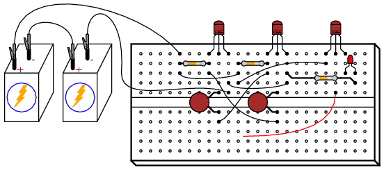
ILLUSTRATION
INSTRUCTIONS
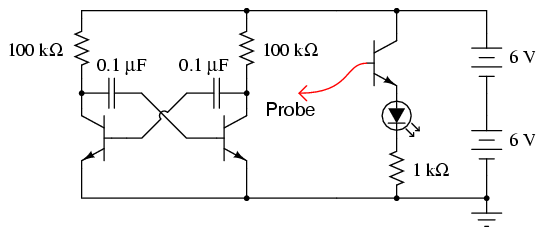
The proper name for this circuit is "astable
multivibrator". It is a simple, free-running oscillator
circuit timed by the sizes of the resistors, capacitors, and
power supply voltage. Unfortunately, its output waveform is
very distorted, neither sine wave nor square. For the simple
purpose of making an audio tone, however, distortion doesn't
matter much.
With a 12 volt supply, 100 kΩ resistors, and
0.1 �F capacitors, the oscillation frequency will be in the
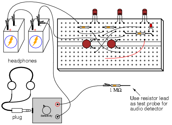
low audio range. You may listen to this signal with the
audio detector connected with one test probe to ground and
the other to one of the transistor's collector terminals. I
recommend placing a 1 MΩ resistor in series with the audio
detector to minimize both circuit loading effects and
headphone loudness:
The multivibrator itself is just two
transistors, two resistors, and two cross-connecting
capacitors. The third transistor shown in the schematic and
illustration is there for driving the LED, to be used as a
visual indicator of oscillator action. Use the probe wire
connected to the base of this common-emitter amplifier to
detect voltage at different parts of the circuit with
respect to ground. Given the low oscillating frequency of
this multivibrator circuit, you should be able to see the
LED blink rapidly with the probe wire connected to the
collector terminal of either multivibrator transistor.
You may notice that the LED fails to blink
with its probe wire touching the base of either
multivibrator transistor, yet the audio detector tells you
there is an oscillating voltage there. Why is this? The
LED's common-collector transistor amplifier is a voltage
follower, meaning that it doesn't amplify voltage. Thus, if
the voltage under test is less than the minimum required by
the LED to light up, it will not glow. Since the
forward-biased base-emitter junction of an active transistor
drops only about 0.7 volts, there is insufficient voltage at
either transistor base to energize the LED. The audio
detector, being extraordinarily sensitive, though, detects
this low voltage signal easily.
Feel free to substitute lower-value
resistors in place of the two 100 kΩ units shown. What
happens to the oscillation frequency when you do so? I
recommend using resistors at least 1 kΩ in size to prevent
excessive transistor current.
One shortcoming of many oscillator circuits
is its dependence on a minimum amount of power supply
voltage. Too little voltage and the circuit ceases to
oscillate. This circuit is no exception. You might want to
experiment with lower supply voltages and determine the
minimum voltage necessary for oscillation, as well as
experience the effect supply voltage change has on
oscillation frequency.
One shortcoming specific to this circuit is
the dependence on mismatched components for successful
starting. In order for the circuit to begin oscillating, one
transistor must turn on before the other one. Usually, there
is enough mismatch in the various component values to enable
this to happen, but it is possible for the circuit to
"freeze" and fail to oscillate at power-up. If this happens,
try different components (same values, but different units)
in the circuit.
|
