Full-wave center-tap rectifier
PARTS AND MATERIALS
-
Low-voltage AC power supply (6 volt
output)
-
Two 1N4001 rectifying diodes (Radio Shack
catalog # 276-1101)
-
Small "hobby" motor, permanent-magnet type
(Radio Shack catalog # 273-223 or equivalent)
-
Audio detector with headphones
-
0.1 �F capacitor
-
One toggle switch, SPST ("Single-Pole,
Single-Throw")
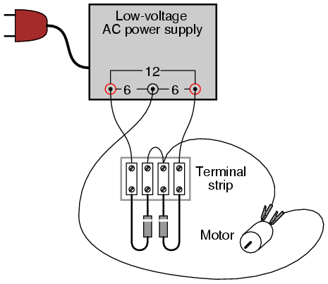
It is essential for this experiment that the
low-voltage AC power supply be equipped with a center tap. A
transformer with a non-tapped secondary winding simply will
not work for this circuit.
The diodes need not be exact model 1N4001
units. Any of the "1N400X" series of rectifying diodes are
suitable for the task, and they are quite easy to obtain.
CROSS-REFERENCES
Lessons In Electric Circuits, Volume
3, chapter 3: "Diodes and Rectifiers"
LEARNING OBJECTIVES
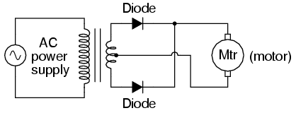
SCHEMATIC DIAGRAM
ILLUSTRATION
INSTRUCTIONS
This rectifier circuit is called
full-wave because it makes use of the entire waveform,
both positive and negative half-cycles, of the AC source
voltage in powering the DC load. As a result, there is less
"ripple" voltage seen at the load. The RMS
(Root-Mean-Square) value of the rectifier's output is also
greater for this circuit than for the half-wave rectifier.
Use a voltmeter to measure both the DC and
AC voltage delivered to the motor. You should notice the
advantages of the full-wave rectifier immediately by the
greater DC and lower AC indications as compared to the last
experiment.
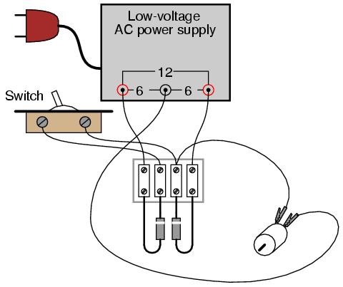
An experimental advantage of this circuit is
the ease of which it may be "de-converted" to a half-wave
rectifier: simply disconnect the short jumper wire
connecting the two diodes' cathode ends together on the
terminal strip. Better yet, for quick comparison between
half and full-wave rectification, you may add a switch in
the circuit to open and close this connection at will:
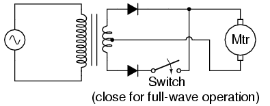
With the ability to quickly switch between
half- and full-wave rectification, you may easily perform
qualitative comparisons between the two different operating
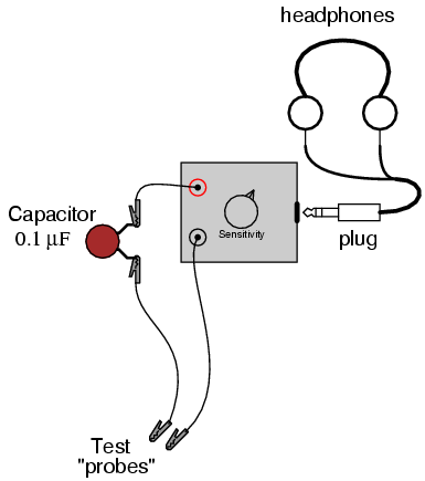
modes. Use the audio signal detector to "listen" to the
ripple voltage present between the motor terminals for
half-wave and full-wave rectification modes, noting both the
intensity and the quality of the tone. Remember to use a
coupling capacitor in series with the detector so that it
only receives the AC "ripple" voltage and not DC voltage:
COMPUTER SIMULATION
Schematic with SPICE node numbers:
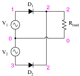
Netlist (make a text file containing the
following text, verbatim):
Fullwave center-tap rectifier
v1 1 0 sin(0 8.485 60 0 0)
v2 0 3 sin(0 8.485 60 0 0)
rload 2 0 10k
d1 1 2 mod1
d2 3 2 mod1
.model mod1 d
.tran .5m 25m
.plot tran v(1,0) v(2,0)
.end
|
