JFET current regulator
PARTS AND MATERIALS
-
One N-channel junction field-effect
transistor, models 2N3819 or J309 recommended (Radio Shack
catalog # 276-2035 is the model 2N3819)
-
Two 6-volt batteries
-
One 10 kΩ potentiometer, single-turn,
linear taper (Radio Shack catalog # 271-1715)
-
One 1 kΩ resistor
-
One 10 kΩ resistor
-
Three 1.5 kΩ resistors
For this experiment you will need an
N-channel JFET, not a P-channel!
Beware that not all transistors share the
same terminal designations, or pinouts, even if they
share the same physical appearance. This will dictate how
you connect the transistors together and to other
components, so be sure to check the manufacturer's
specifications (component datasheet), easily obtained from
the manufacturer's website. Beware that it is possible for
the transistor's package and even the manufacturer's
datasheet to show incorrect terminal identification
diagrams! Double-checking pin identities with your
multimeter's "diode check" function is highly recommended.
For details on how to identify junction field-effect
transistor terminals using a multimeter, consult chapter 5
of the Semiconductor volume (volume III) of this book
series.
CROSS-REFERENCES
Lessons In Electric Circuits, Volume
3, chapter 5: "Junction Field-Effect Transistors"
Lessons In Electric Circuits, Volume
3, chapter 3: "Diodes and Rectifiers"
LEARNING OBJECTIVES
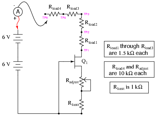
SCHEMATIC DIAGRAM
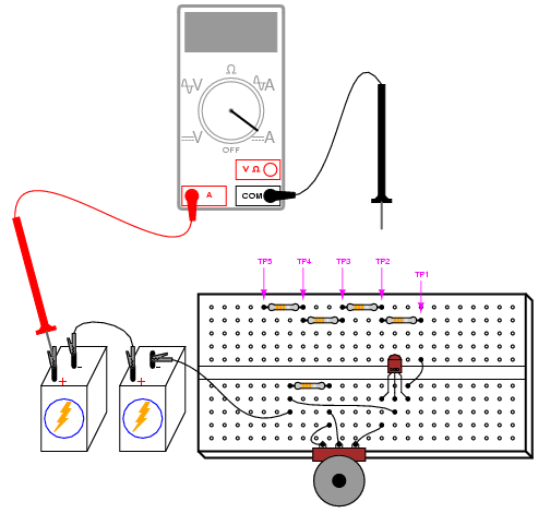
ILLUSTRATION
INSTRUCTIONS
Previously in this chapter, you saw how a
pair of bipolar junction transistors (BJTs) could be used to
form a current mirror, whereby one transistor would
try to maintain the same current through it as through the
other, the other's current level being established by a
variable resistance. This circuit performs the same task of
regulating current, but uses a single junction field-effect
transistor (JFET) instead of two BJTs.
The two series resistors Radjust
and Rlimit set the current regulation point,
while the load resistors and the test points between them
serve only to demonstrate constant current despite changes
in load resistance.
To begin the experiment, touch the test
probe to TP4 and adjust the potentiometer through its range
of travel. You should see a small, changing current
indicated by your ammeter as you move the potentiometer
mechanism: no more than a few milliamps. Leave the
potentiometer set to a position giving a round number of
milliamps and move the meter's black test probe to TP3. The
current indication should be very nearly the same as before.
Move the probe to TP2, then TP1. Again, you should see a
nearly unchanged amount of current. Try adjusting the
potentiometer to another position, giving a different
current indication, and touch the meter's black probe to
test points TP1 through TP4, noting the stability of the
current indications as you change load resistance. This
demonstrates the current regulating behavior of this
circuit.
TP5, at the end of a 10 kΩ resistor, is
provided for introducing a large change in load resistance.
Connecting the black test probe of your ammeter to that test
point gives a combined load resistance of 14.5 kΩ, which
will be too much resistance for the transistor to maintain
maximum regulated current through. To experience what I'm
describing here, touch the black test probe to TP1 and
adjust the potentiometer for maximum current. Now, move the
black test probe to TP2, then TP3, then TP4. For all these
test point positions, the current will remain approximately
constant. However, when you touch the black probe to TP5,
the current will fall dramatically. Why? Because at this
level of load resistance, there is insufficient voltage drop
across the transistor to maintain regulation. In other
words, the transistor will be saturated as it attempts to
provide more current than the circuit resistance will allow.
Move the black test probe back to TP1 and
adjust the potentiometer for minimum current. Now, touch the
black test probe to TP2, then TP3, then TP4, and finally
TP5. What do you notice about the current indication at all
these points? When the current regulation point is adjusted
to a lesser value, the transistor is able to maintain
regulation over a much larger range of load resistance.
An important caveat with the BJT current
mirror circuit is that both transistors must be at equal
temperature for the two currents to be equal. With this
circuit, however, transistor temperature is almost
irrelevant. Try grasping the transistor between your fingers
to heat it up, noting the load current with your ammeter.
Try cooling it down afterward by blowing on it. Not only is
the requirement of transistor matching eliminated (due to
the use of just one transistor), but the thermal
effects are all but eliminated as well due to the relative
thermal immunity of the field-effect transistor. This
behavior also makes field-effect transistors immune to
thermal runaway; a decided advantage over bipolar junction
transistors.
An interesting application of this
current-regulator circuit is the so-called
constant-current diode. Described in the "Diodes and
Rectifiers" chapter of volume III, this diode isn't really a
PN junction device at all. Instead, it is a JFET with a
fixed resistance connected between the gate and source
terminals:
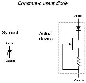
A normal PN-junction diode is included in
series with the JFET to protect the transistor against
damage from reverse-bias voltage, but otherwise the
current-regulating facility of this device is entirely
provided by the field-effect transistor.
COMPUTER SIMULATION
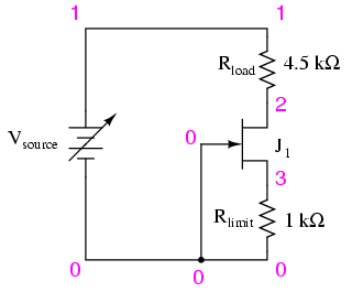
Schematic with SPICE node numbers:
Netlist (make a text file containing the
following text, verbatim):
JFET current regulator
vsource 1 0
rload 1 2 4.5k
j1 2 0 3 mod1
rlimit 3 0 1k
.model mod1 njf
.dc vsource 6 12 0.1
.plot dc i(vsource)
.end
SPICE does not allow for "sweeping"
resistance values, so to demonstrate the current regulation
of this circuit over a wide range of conditions, I've
elected to sweep the source voltage from 6 to 12 volts in
0.1 volt steps. If you wish, you can set rload to
different resistance values and verify that the circuit
current remains constant. With an rlimit value of 1
kΩ, the regulated current will be 291.8 �A. This current
figure will most likely not be the same as your
actual circuit current, due to differences in JFET
parameters.
Many manufacturers give SPICE model
parameters for their transistors, which may be typed in the
.model line of the netlist for a more accurate
circuit simulation.
|
