Current mirror
PARTS AND MATERIALS
-
Two NPN transistors -- models 2N2222 or
2N3403 recommended (Radio Shack catalog # 276-1617 is a
package of fifteen NPN transistors ideal for this and
other experiments)
-
Two 6-volt batteries
-
One 10 kΩ potentiometer, single-turn,
linear taper (Radio Shack catalog # 271-1715)
-
Two 10 kΩ resistors
-
Four 1.5 kΩ resistors
Small signal transistors are recommended so
as to be able to experience "thermal runaway" in the latter
portion of the experiment. Larger "power" transistors may
not exhibit the same behavior at these low current levels.
However, any pair of identical NPN transistors may be
used to build a current mirror.
Beware that not all transistors share the
same terminal designations, or pinouts, even if they
share the same physical appearance. This will dictate how
you connect the transistors together and to other
components, so be sure to check the manufacturer's
specifications (component datasheet), easily obtained from
the manufacturer's website. Beware that it is possible for
the transistor's package and even the manufacturer's
datasheet to show incorrect terminal identification
diagrams! Double-checking pin identities with your
multimeter's "diode check" function is highly recommended.
For details on how to identify bipolar transistor terminals
using a multimeter, consult chapter 4 of the Semiconductor
volume (volume III) of this book series.
CROSS-REFERENCES
Lessons In Electric Circuits, Volume
3, chapter 4: "Bipolar Junction Transistors"
LEARNING OBJECTIVES
-
How to build a current mirror circuit
-
Current limitations of a current mirror
circuit
-
Temperature dependence of BJTs
-
Experience a controlled "thermal runaway"
situation
SCHEMATIC DIAGRAM
ILLUSTRATION
INSTRUCTIONS
A current mirror may be thought of as an
adjustable current regulator, the current limit being
easily set by a single resistance. It is a rather crude
current regulator circuit, but one that finds wide use due
to its simplicity. In this experiment, you will get the
opportunity to build one of these circuits, explore its
current-regulating properties, and also experience some of
its practical limitations firsthand.
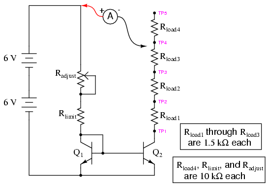
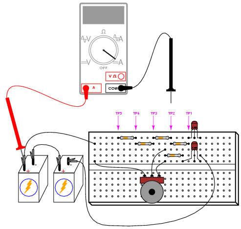
Build the circuit as shown in the schematic
and illustration. You will have one extra 1.5 kΩ fixed-value
resistor from the parts specified in the parts list. You
will be using it in the last part of this experiment.
The potentiometer sets the amount of current
through transistor Q1. This transistor is
connected to act as a simple diode: just a PN junction. Why
use a transistor instead of a regular diode? Because it is
important to match the junction characteristics of
these two transistors when using them in a current mirror
circuit. Voltage dropped across the base-emitter junction of
Q1 is impressed across the base-emitter junction
of the other transistor, Q2, causing it to turn
"on" and likewise conduct current.
Since voltage across the two transistors'
base-emitter junctions is the same -- the two junction pairs
being connected in parallel with each other -- so should the
current be through their base terminals, assuming identical
junction characteristics and identical junction
temperatures. Matched transistors should have the same β
ratios, as well, so equal base currents means equal
collector currents. The practical result of all this is Q2's
collector current mimicking whatever current magnitude has
been established through the collector of Q1 by
the potentiometer. In other words, current through Q2
mirrors the current through Q1.
Changes in load resistance (resistance
connecting the collector of Q2 to the positive
side of the battery) have no effect on Q1's
current, and consequently have no effect upon the
base-emitter voltage or base current of Q2. With
a constant base current and a nearly constant β ratio, Q2
will drop as much or as little collector-emitter voltage as
necessary to hold its collector (load) current constant.
Thus, the current mirror circuit acts to regulate
current at a value set by the potentiometer, without regard
to load resistance.
Well, that is how it is supposed to work,
anyway. Reality isn't quite so simple, as you are about to
see. In the circuit diagram shown, the load circuit of Q2
is completed to the positive side of the battery through an
ammeter, for easy current measurement. Rather than solidly
connect the ammeter's black probe to a definite point in the
circuit, I've marked five test points, TP1 through
TP5, for you to touch the black test probe to while
measuring current. This allows you to quickly and
effortlessly change load resistance: touching the probe to
TP1 results in practically no load resistance, while
touching it to TP5 results in approximately 14.5 kΩ of load
resistance.
To begin the experiment, touch the test
probe to TP4 and adjust the potentiometer through its range
of travel. You should see a small, changing current
indicated by your ammeter as you move the potentiometer
mechanism: no more than a few milliamps. Leave the
potentiometer set to a position giving a round number of
milliamps and move the meter's black test probe to TP3. The
current indication should be very nearly the same as before.
Move the probe to TP2, then TP1. Again, you should see a
nearly unchanged amount of current. Try adjusting the
potentiometer to another position, giving a different
current indication, and touch the meter's black probe to
test points TP1 through TP4, noting the stability of the
current indications as you change load resistance. This
demonstrates the current regulating behavior of this
circuit.
You should note that the current regulation
isn't perfect. Despite regulating the current at nearly
the value for load resistances between 0 and 4.5 kΩ, there
is some variation over this range. The regulation may be
much worse if load resistance is allowed to rise too high.
Try adjusting the potentiometer so that maximum current is
obtained, as indicated with the ammeter test probe connected
to TP1. Leaving the potentiometer at that position, move the
meter probe to TP2, then TP3, then TP4, and finally TP5,
noting the meter's indication at each connection point. The
current should be regulated at a nearly constant value until
the meter probe is moved to the last test point, TP5. There,
the current indication will be substantially lower than at
the other test points. Why is this? Because too much load
resistance has been inserted into Q2's circuit.
Simply put, Q2 cannot "turn on" any more than it
already has, to maintain the same amount of current with
this great a load resistance as with lesser load
resistances.
This phenomenon is common to all
current-regulator circuits: there is a limited amount of
resistance a current regulator can handle before it
saturates. This stands to reason, as any current
regulator circuit capable of supplying a constant amount of
current through any load resistance imaginable would
require an unlimited source of voltage to do it! Ohm's Law
(E=IR) dictates the amount of voltage needed to push a given
amount of current through a given amount of resistance, and
with only 12 volts of power supply voltage at our disposal,
a finite limit of load current and load resistance
definitely exists for this circuit. For this reason, it may
be helpful to think of current regulator circuits as being
current limiter circuits, for all they can really do
is limit current to some maximum value.
An important caveat for current mirror
circuits in general is that of equal temperature between the
two transistors. The current "mirroring" taking place
between the two transistors' collector circuits depends on
the base-emitter junctions of those two transistors having
the exact same properties. As the "diode equation"
describes, the voltage/current relationship for a PN
junction strongly depends on junction temperature.
The hotter a PN junction is, the more current it will pass
for a given amount of voltage drop. If one transistor should
become hotter than the other, it will pass more collector
current than the other, and the circuit will no longer
"mirror" current as expected. When building a real current
mirror circuit using discrete transistors, the two
transistors should be epoxy-glued together (back-to-back) so
that they remain at approximately the same temperature.
To illustrate this dependence on equal
temperature, try grasping one transistor between your
fingers to heat it up. What happens to the current through
the load resistors as the transistor's temperature
increases? Now, let go of the transistor and blow on it to
cool it down to ambient temperature. Grasp the other
transistor between your fingers to heat it up. What does the
load current do now?
In this next phase of the experiment, we
will intentionally allow one of the transistors to overheat
and note the effects. To avoid damaging a transistor, this
procedure should be conducted no longer than is necessary to
observe load current begin to "run away." To begin, adjust
the potentiometer for minimum current. Next, replace the 10
kΩ Rlimit resistor with a 1.5 kΩ resistor. This
will allow a higher current to pass through Q1,
and consequently through Q2 as well.
Place the ammeter's black probe on TP1 and
observe the current indication. Move the potentiometer in
the direction of increasing current until you read about 10
mA through the ammeter. At that point, stop moving the
potentiometer and just observe the current. You will notice
current begin to increase all on its own, without further
potentiometer motion! Break the circuit by removing the
meter probe from TP1 when the current exceeds 30 mA, to
avoid damaging transistor Q2.
If you carefully touch both transistors with
a finger, you should notice Q2 is warm, while Q1
is cool. Warning: if Q2's current has been
allowed to "run away" too far or for too long a time, it may
become very hot! You can receive a bad burn on your
fingertip by touching an overheated semiconductor component,
so be careful here!
What just happened to make Q2
overheat and lose current control? By connecting the ammeter
to TP1, all load resistance was removed, so Q2
had to drop full battery voltage between collector and
emitter as it regulated current. Transistor Q1 at
least had the 1.5 kΩ resistance of Rlimit in
place to drop most of the battery voltage, so its power
dissipation was far less than that of Q2. This
gross imbalance of power dissipation caused Q2 to
heat more than Q1. As the temperature increased,
Q2 began to pass more current for the same amount
of base-emitter voltage drop. This caused it to heat up even
faster, as it was passing more collector current while still
dropping the full 12 volts between collector and emitter.
The effect is known as thermal runaway, and it is
possible in many bipolar junction transistor circuits, not
just current mirrors.
COMPUTER SIMULATION
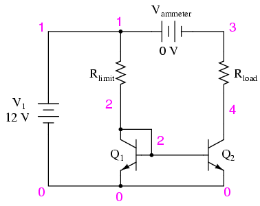
Schematic with SPICE node numbers:
Netlist (make a text file containing the following text,
verbatim):
Current mirror
v1 1 0
vammeter 1 3 dc 0
rlimit 1 2 10k
rload 3 4 3k
q1 2 2 0 mod1
q2 4 2 0 mod1
.model mod1 npn bf=100
.dc v1 12 12 1
.print dc i(vammeter)
.end
Vammeter is nothing more than a
zero-volt DC battery strategically placed to intercept load
current. This is nothing more than a trick to measure
current in a SPICE simulation, as no dedicated "ammeter"
component exists in the SPICE language.
It is important to remember that SPICE only
recognizes the first eight characters of a component's name.
The name "vammeter" is okay, but if we were to incorporate
more than one current-measuring voltage source in the
circuit and name them "vammeter1" and "vammeter2",
respectively, SPICE would see them as being two instances of
the same component "vammeter" (seeing only the first eight
characters) and halt with an error. Something to bear in
mind when altering the netlist or programming your own SPICE
simulation!
You will have to experiment with different
resistance values of Rload in this simulation to
appreciate the current-regulating nature of the circuit.
With Rlimit set to 10 kΩ and a power supply
voltage of 12 volts, the regulated current through Rload
will be 1.1 mA. SPICE shows the regulation to be perfect
(isn't the virtual world of computer simulation so nice?),
the load current remaining at 1.1 mA for a wide range
of load resistances. However, if the load resistance is
increased beyond 10 kΩ, even this simulation shows the load
current suffering a decrease as in real life.
|
