Rectifier/filter circuit
PARTS AND MATERIALS
-
Low-voltage AC power supply
-
Bridge rectifier pack (Radio Shack catalog
# 276-1185 or equivalent)
-
Electrolytic capacitor, 1000 �F, at least
25 WVDC (Radio Shack catalog # 272-1047 or equivalent)
-
Four "banana" jack style binding posts, or
other terminal hardware, for connection to potentiometer
circuit (Radio Shack catalog # 274-662 or equivalent)
-
Metal box
-
12-volt light bulb, 25 watt
-
Lamp socket
A bridge rectifier "pack" is highly
recommended over constructing a bridge rectifier circuit
from individual diodes, because such "packs" are made to
bolt onto a metal heat sink. A metal box is recommended over
a plastic box for its ability to function as a heat sink for
the rectifier.
A larger capacitor value is fine to use in
this experiment, so long as its working voltage is high
enough. To be safe, choose a capacitor with a working
voltage rating at least twice the RMS AC voltage output of
the low-voltage AC power supply.
High-wattage 12-volt lamps may be purchased
from recreational vehicle (RV) and boating supply stores.
Common sizes are 25 watt and 50 watt. This lamp will be used
as a "heavy" load for the power supply.
CROSS-REFERENCES
Lessons In Electric Circuits, Volume
2, chapter 8: "Filters"
LEARNING OBJECTIVES
SCHEMATIC DIAGRAM
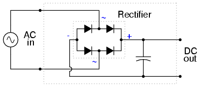
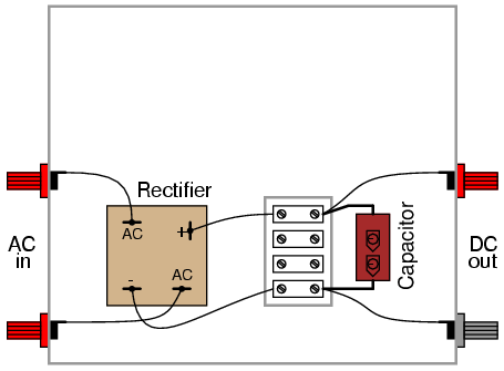
ILLUSTRATION
INSTRUCTIONS
This experiment involves constructing a
rectifier and filter circuit for attachment to the
low-voltage AC power supply constructed earlier. With this
device, you will have a source of low-voltage, DC power
suitable as a replacement for a battery in battery-powered
experiments. If you would like to make this device its own,
self-contained 120VAC/DC power supply, you may add all the
componentry of the low-voltage AC supply to the "AC in" side
of this circuit: a transformer, power cord, and plug. Even
if you don't choose to do this, I recommend using a metal
box larger than necessary to provide room for additional
voltage regulation circuitry you might choose to add to this
project later.
The bridge rectifier unit should be rated
for a current at least as high as the transformer's
secondary winding is rated for, and for a voltage at least
twice as high as the RMS voltage of the transformer's output
(this allows for peak voltage, plus an additional safety
margin). The Radio Shack rectifier specified in the parts
list is rated for 25 amps and 50 volts, more than enough for
the output of the low-voltage AC power supply specified in
the AC experiments chapter.
Rectifier units of this size are often
equipped with "quick-disconnect" terminals. Complementary
"quick-disconnect" lugs are sold that crimp onto the bare
ends of wire. This is the preferred method of terminal
connection. You may solder wires directly to the lugs of the
rectifier, but I recommend against direct soldering to any
semiconductor component for two reasons: possible heat
damage during soldering, and difficulty of replacing the
component in the event of failure.
Semiconductor devices are more prone to
failure than most of the components covered in these
experiments thus far, and so if you have any intent of
making a circuit permanent, you should build it to be
maintained. "Maintainable construction" involves, among
other things, making all delicate components replaceable. It
also means making "test points" accessible to meter probes
throughout the circuit, so that troubleshooting may be
executed with a minimum of inconvenience. Terminal strips
inherently provide test points for taking voltage
measurements, and they also allow for easy disconnection of
wires without sacrificing connection durability.
Bolt the rectifier unit to the inside of the
metal box. The box's surface area will act as a radiator,
keeping the rectifier unit cool as it passes high currents.
Any metal radiator surface designed to lower the operating
temperature of an electronic component is called a heat
sink. Semiconductor devices in general are prone to
damage from overheating, so providing a path for heat
transfer from the device(s) to the ambient air is very
important when the circuit in question may handle large
amounts of power.
A capacitor is included in the circuit to
act as a filter to reduce ripple voltage. Make sure
that you connect the capacitor properly across the DC output
terminals of the rectifier, so that the polarities match.
Being an electrolytic capacitor, it is sensitive to damage
by polarity reversal. In this circuit especially, where the
internal resistance of the transformer and rectifier are low
and the short-circuit current consequently is high, the
potential for damage is great. Warning: a failed
capacitor in this circuit will likely explode with alarming
force!
After the rectifier/filter circuit is built,
connect it to the low-voltage AC power supply like this:
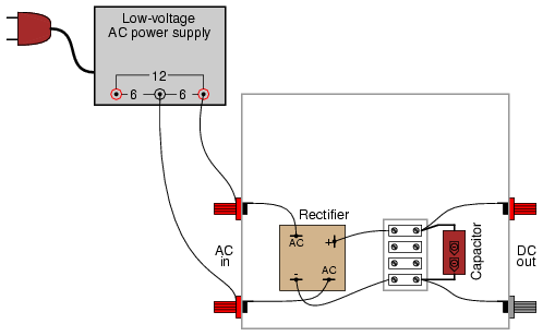
Measure the AC voltage output by the
low-voltage power supply. Your meter should indicate
approximately 6 volts if the circuit is connected as shown.
This voltage measurement is the RMS voltage of the AC power
supply.
Now, switch your multimeter to the DC
voltage function and measure the DC voltage output by the
rectifier/filter circuit. It should read substantially
higher than the RMS voltage of the AC input measured before.
The filtering action of the capacitor provides a DC output
voltage equal to the peak AC voltage, hence the
greater voltage indication:
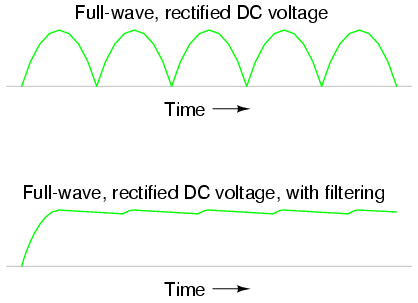
Measure the AC ripple voltage magnitude with
a digital voltmeter set to AC volts (or AC millivolts). You
should notice a much smaller ripple voltage in this circuit
than what was measured in any of the unfiltered rectifier
circuits previously built. Feel free to use your audio
detector to "listen" to the AC ripple voltage output by the
rectifier/filter unit. As usual, connect a small "coupling"
capacitor in series with the detector so that it does not
respond to the DC voltage, but only the AC ripple. Very
little sound should be heard.
After taking unloaded AC ripple voltage
measurements, connect the 25 watt light bulb to the output
of the rectifier/filter circuit like this:

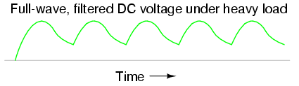
Re-measure the ripple voltage present
between the rectifier/filter unit's "DC out" terminals. With
a heavy load, the filter capacitor becomes discharged
between rectified voltage peaks, resulting in greater ripple
than before:
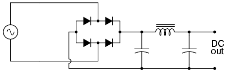
If less ripple is desired under heavy-load
conditions, a larger capacitor may be used, or a more
complex filter circuit may be built using two capacitors and
an inductor:
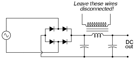
If you choose to build such a filter
circuit, be sure to use an iron-core inductor for maximum
inductance, and one with thick enough wire to safely handle
the full rated current of power supply. Inductors used for
the purpose of filtering are sometimes referred to as
chokes, because they "choke" AC ripple voltage from
getting to the load. If a suitable choke cannot be obtained,
the secondary winding of a step-down power transformer like
the type used to step 120 volts AC down to 12 or 6 volts AC
in the low-voltage power supply may be used. Leave the
primary (120 volt) winding open:
COMPUTER SIMULATION
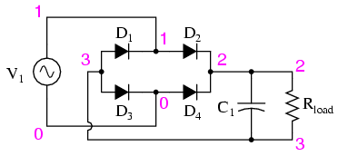
Schematic with SPICE node numbers:
Netlist (make a text file containing the
following text, verbatim):
Fullwave bridge rectifier
v1 1 0 sin(0 8.485 60 0 0)
rload 2 3 10k
c1 2 3 1000u ic=0
d1 3 1 mod1
d2 1 2 mod1
d3 3 0 mod1
d4 0 2 mod1
.model mod1 d
.tran .5m 25m
.plot tran v(1,0) v(2,3)
.end
You may decrease the value of Rload
in the simulation from 10 kΩ to some lower value to explore
the effects of loading on ripple voltage. As it is with a 10
kΩ load resistor, the ripple is undetectable on the waveform
plotted by SPICE.
|
