Connecting digital circuitry to sensor devices
is simple if the sensor devices are inherently digital themselves. Switches,
relays, and encoders are easily interfaced with gate circuits due to the
on/off nature of their signals. However, when analog devices are involved,
interfacing becomes much more complex. What is needed is a way to
electronically translate analog signals into digital (binary) quantities,
and visa-versa. An analog-to-digital converter, or ADC, performs the
former task while a digital-to-analog converter, or DAC, performs the
latter.
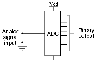
An ADC inputs an analog electrical signal such as voltage or current and
outputs a binary number. In block diagram form, it can be represented as
such:
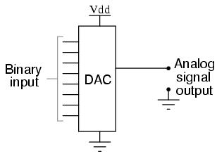
A DAC, on the other hand, inputs a binary number and outputs an analog
voltage or current signal. In block diagram form, it looks like this:
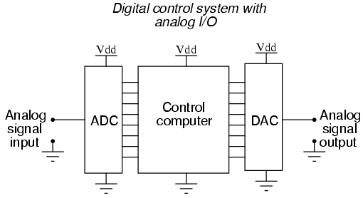
Together, they are often used in digital systems to provide complete
interface with analog sensors and output devices for control systems such as
those used in automotive engine controls:
It is much easier to convert a digital signal into an analog signal than
it is to do the reverse. Therefore, we will begin with DAC circuitry and
then move to ADC circuitry. |
