Potentiometer as a rheostat
PARTS AND MATERIALS
-
6 volt battery
-
Potentiometer, single turn, 5 kΩ, linear
taper (Radio Shack catalog # 271-1714)
-
Small "hobby" motor, permanent-magnet type
(Radio Shack catalog # 273-223 or equivalent)
For this experiment, you will need a
relatively low-value potentiometer, certainly not more than
5 kΩ.
CROSS-REFERENCES
Lessons In Electric Circuits, Volume
1, chapter 2: "Ohm's Law"
LEARNING OBJECTIVES
-
Rheostat use
-
Wiring a potentiometer as a rheostat
-
Simple motor speed control
-
Use of voltmeter over ammeter to verify a
continuous circuit
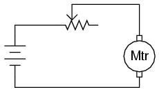
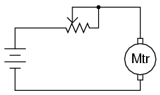
SCHEMATIC DIAGRAM

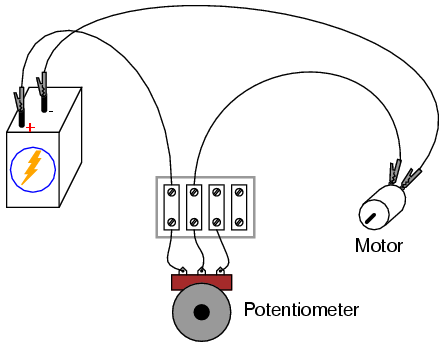
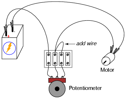
ILLUSTRATION

INSTRUCTIONS
Potentiometers find their most sophisticated
application as voltage dividers, where shaft position
determines a specific voltage division ratio. However, there
are applications where we don't necessarily need a variable
voltage divider, but merely a variable resistor: a
two-terminal device. Technically, a variable resistor is
known as a rheostat, but potentiometers can be made
to function as rheostats quite easily.
In its simplest configuration, a
potentiometer may be used as a rheostat by simply using the
wiper terminal and one of the other terminals, the third
terminal left unconnected and unused:
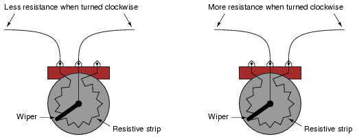
Moving the potentiometer control in the
direction that brings the wiper closest to the other used
terminal results in a lower resistance. The direction of
motion required to increase or decrease resistance may be
changed by using a different set of terminals:
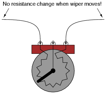
Be careful, though, that you don't use the
two outer terminals, as this will result in no change in
resistance as the potentiometer shaft is turned. In
other words, it will no longer function as a variable
resistance:
Build the circuit as shown in the schematic
and illustration, using just two terminals on the
potentiometer, and see how motor speed may be controlled by
adjusting shaft position. Experiment with different terminal
connections on the potentiometer, noting the changes in
motor speed control. If your potentiometer has a high
resistance (as measured between the two outer terminals),
the motor might not move at all until the wiper is brought
very close to the connected outer terminal.
As you can see, motor speed may be made
variable using a series-connected rheostat to change total
circuit resistance and limit total current. This simple
method of motor speed control, however, is inefficient, as
it results in substantial amounts of power being dissipated
(wasted) by the rheostat. A much more efficient means of
motor control relies on fast "pulsing" of power to the
motor, using a high-speed switching device such as a
transistor. A similar method of power control is used in
household light "dimmer" switches. Unfortunately, these
techniques are much too sophisticated to explore at this
point in the experiments.
When a potentiometer is used as a rheostat,
the "unused" terminal is often connected to the wiper
terminal, like this:
At first, this seems rather pointless, as it
has no impact on resistance control. You may verify this
fact for yourself by inserting another wire in your circuit
and comparing motor behavior before and after the change:
If the potentiometer is in good working
order, this additional wire makes no difference whatsoever.
However, if the wiper ever loses contact with the resistive
strip inside the potentiometer, this connection ensures the
circuit does not completely open: that there will still be a
resistive path for current through the motor. In some
applications, this may be an important. Old potentiometers
tend to suffer from intermittent losses of contact between
the wiper and the resistive strip, and if a circuit cannot
tolerate the complete loss of continuity (infinite
resistance) created by this condition, that "extra" wire
provides a measure of protection by maintaining circuit
continuity.
You may simulate such a wiper contact
"failure" by disconnecting the potentiometer's middle
terminal from the terminal strip, measuring voltage across
the motor to ensure there is still power getting to it,
however small:

It would have been valid to measure circuit
current instead of motor voltage to verify a completed
circuit, but this is a safer method because it does not
involve breaking the circuit to insert an ammeter in series.
Whenever an ammeter is used, there is risk of causing a
short circuit by connecting it across a substantial voltage
source, possibly resulting in instrument damage or personal
injury. Voltmeters lack this inherent safety risk, and so
whenever a voltage measurement may be made instead of a
current measurement to verify the same thing, it is the
wiser choice. |
