Potentiometer as a voltage divider
PARTS AND MATERIALS
-
Two 6-volt batteries
-
Carbon pencil "lead" for a
mechanical-style pencil
-
Potentiometer, single turn, 5 kΩ to 50 kΩ,
linear taper (Radio Shack catalog # 271-1714 through
271-1716)
-
Potentiometer, multi turn, 1 kΩ to 20 kΩ,
(Radio Shack catalog # 271-342, 271-343, 900-8583, or
900-8587 through 900-8590)
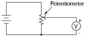
Potentiometers are variable voltage dividers
with a shaft or slide control for setting the division
ratio. They are manufactured in panel-mount as well as
breadboard (printed-circuit board) mount versions. Any style
of potentiometer will suffice for this experiment.
If you salvage a potentiometer from an old
radio or other audio device, you will likely be getting what
is called an audio taper potentiometer. These
potentiometers exhibit a logarithmic relationship between
division ratio and shaft position. By contrast, a linear
potentiometer exhibits a direct correlation between shaft
position and voltage division ratio. I highly recommend a
linear potentiometer for this experiment, and for most
experiments in general.
CROSS-REFERENCES
Lessons In Electric Circuits, Volume
1, chapter 6: "Divider Circuits and Kirchhoff's Laws"
LEARNING OBJECTIVES
SCHEMATIC DIAGRAM
ILLUSTRATION
INSTRUCTIONS
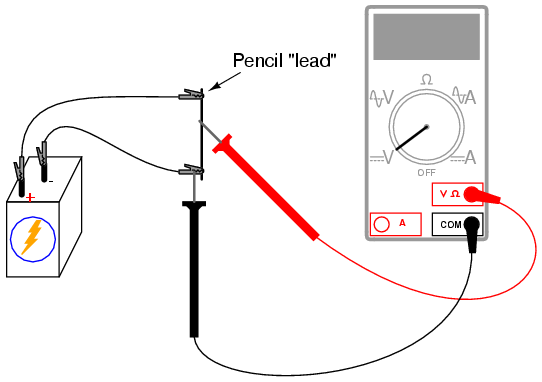
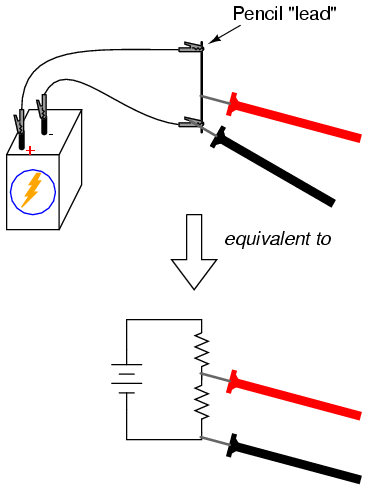
Begin this experiment with the pencil "lead"
circuit. Pencils use a rod made of a graphite-clay mixture,
not lead (the metal), to make black marks on paper.
Graphite, being a mediocre electrical conductor, acts as a
resistor connected across the battery by the two
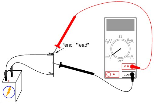
alligator-clip jumper wires. Connect the voltmeter as shown
and touch the red test probe to the graphite rod. Move the
red probe along the length of the rod and notice the
voltmeter's indication change. What probe position gives the
greatest voltage indication?
Essentially, the rod acts as a pair
of resistors, the ratio between the two resistances
established by the position of the red test probe along the
rod's length:
Now, change the voltmeter connection to the
circuit so as to measure voltage across the "upper resistor"
of the pencil lead, like this:
Move the black test probe position along the
length of the rod, noting the voltmeter indication. Which
position gives the greatest voltage drop for the meter to
measure? Does this differ from the previous arrangement?
Why?
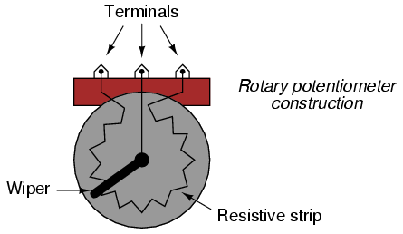
Manufactured potentiometers enclose a
resistive strip inside a metal or plastic housing, and
provide some kind of mechanism for moving a "wiper" across
the length of that resistive strip. Here is an illustration
of a rotary potentiometer's construction:
Some rotary potentiometers have a spiral
resistive strip, and a wiper that moves axially as it
rotates, so as to require multiple turns of the shaft to
drive the wiper from one end of the potentiometer's range to
the other. Multi-turn potentiometers are used in
applications where precise setting is important.
Linear potentiometers also contain a
resistive strip, the only difference being the wiper's
direction of travel. Some linear potentiometers use a slide
mechanism to move the wiper, while others a screw, to
facilitate multiple-turn operation:
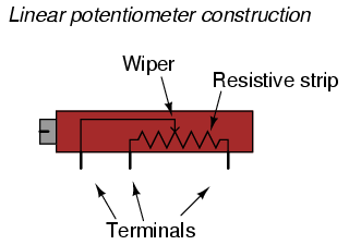
It should be noted that not all linear
potentiometers have the same pin assignments. On some, the
middle pin is the wiper.
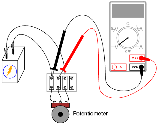
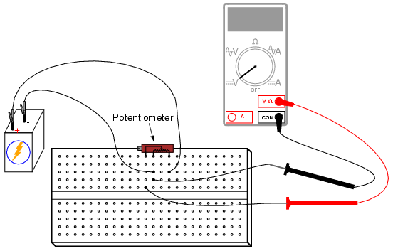
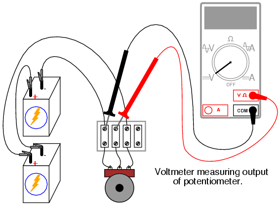
Set up a circuit using a manufactured
potentiometer, not the "home-made" one made from a pencil
lead. You may use any form of construction that is
convenient.
Measure battery voltage while powering the
potentiometer, and make note of this voltage figure on
paper. Measure voltage between the wiper and the
potentiometer end connected to the negative (-) side of the
battery. Adjust the potentiometer mechanism until the
voltmeter registers exactly 1/3 of total voltage. For a
6-volt battery, this will be approximately 2 volts.
Now, connect two batteries in a
series-aiding configuration, to provide approximately 12
volts across the potentiometer. Measure the total battery
voltage, and then measure the voltage between the same two
points on the potentiometer (wiper and negative side).
Divide the potentiometer's measured output voltage by the
measured total voltage. The quotient should be 1/3, the same
voltage division ratio as was set previously:
|
