Potentiometric voltmeter
PARTS AND MATERIALS
-
Two 6 volt batteries
-
One potentiometer, single turn, 10 kΩ,
linear taper (Radio Shack catalog # 271-1715)
-
Two high-value resistors (at least 1 MΩ
each)
-
Sensitive voltage detector (from previous
experiment)
-
Analog voltmeter (from previous
experiment)
The potentiometer value is not critical:
anything from 1 kΩ to 100 kΩ is acceptable. If you have
built the "precision potentiometer" described earlier in
this chapter, it is recommended that you use it in this
experiment.
Likewise, the actual values of the resistors
are not critical. In this particular experiment, the greater
the value, the better the results. They need not be
precisely equal value, either.
If you have not yet built the sensitive
voltage detector, it is recommended that you build one
before proceeding with this experiment! It is a very useful,
yet simple, piece of test equipment that you should not be
without. You can use a digital multimeter set to the "DC
millivolt" (DC mV) range in lieu of a voltage detector, but
the headphone-based voltage detector is more appropriate
because it demonstrates how you can make precise voltage
measurements without using expensive or advanced
meter equipment. I recommend using your home-made multimeter
for the same reason, although any voltmeter will suffice for
this experiment.
CROSS-REFERENCES
Lessons In Electric Circuits, Volume
1, chapter 8: "DC Metering Circuits"
LEARNING OBJECTIVES
-
Voltmeter loading: its causes and its
solution
-
Using a potentiometer as a source of
variable voltage
-
Potentiometric method of voltage
measurement
SCHEMATIC DIAGRAM
ILLUSTRATION
INSTRUCTIONS
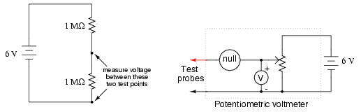
Build the two-resistor voltage divider
circuit shown on the left of the schematic diagram and of
the illustration. If the two high-value resistors are of
equal value, the battery's voltage should be split in half,
with approximately 3 volts dropped across each resistor.
Measure the battery voltage directly with a
voltmeter, then measure each resistor's voltage drop. Do you
notice anything unusual about the voltmeter's readings?
Normally, series voltage drops add to equal the total
applied voltage, but in this case you will notice a serious
discrepancy. Is Kirchhoff's Voltage Law untrue? Is this an
exception to one of the most fundamental laws of electric
circuits? No! What is happening is this: when you connect a
voltmeter across either resistor, the voltmeter itself
alters the circuit so that the voltage is not the same
as with no meter connected.
I like to use the analogy of an air pressure
gauge used to check the pressure of a pneumatic tire. When a
gauge is connected to the tire's fill valve, it releases
some air out of the tire. This affects the pressure in the
tire, and so the gauge reads a slightly lower pressure than
what was in the tire before the gauge was connected. In
other words, the act of measuring tire pressure alters
the tire's pressure. Hopefully, though, there is so little
air released from the tire during the act of measurement
that the reduction in pressure is negligible. Voltmeters
similarly impact the voltage they measure, by bypassing some
current around the component whose voltage drop is being
measured. This affects the voltage drop, but the effect is
so slight that you usually don't notice it.
In this circuit, though, the effect is very
pronounced. Why is this? Try replacing the two high-value
resistors with two of 100 kΩ value each and repeat the
experiment. Replace those resistors with two 10 KΩ units and
repeat. What do you notice about the voltage readings with
lower-value resistors? What does this tell you about
voltmeter "impact" on a circuit in relation to that
circuit's resistance? Replace any low-value resistors with
the original, high-value (>= 1 MΩ) resistors before
proceeding.
Try measuring voltage across the two
high-value resistors -- one at a time -- with a digital
voltmeter instead of an analog voltmeter. What do you notice
about the digital meter's readings versus the analog
meter's? Digital voltmeters typically have greater internal
(probe-to-probe) resistance, meaning they draw less current
than a comparable analog voltmeter when measuring the same
voltage source. An ideal voltmeter would draw zero current
from the circuit under test, and thus suffer no voltage
"impact" problems.
If you happen to have two voltmeters, try
this: connect one voltmeter across one resistor, and the
other voltmeter across the other resistor. The voltage
readings you get will add up to the total voltage this time,
no matter what the resistor values are, even though they're
different from the readings obtained from a single meter
used twice. Unfortunately, though, it is unlikely that the
voltage readings obtained this way are equal to the true
voltage drops with no meters connected, and so it is not a
practical solution to the problem.
Is there any way to make a "perfect"
voltmeter: one that has infinite resistance and draws no
current from the circuit under test? Modern laboratory
voltmeters approach this goal by using semiconductor
"amplifier" circuits, but this method is too technologically
advanced for the student or hobbyist to duplicate. A much
simpler and much older technique is called the
potentiometric or null-balance method. This
involves using an adjustable voltage source to "balance" the
measured voltage. When the two voltages are equal, as
indicated by a very sensitive null detector, the
adjustable voltage source is measured with an ordinary
voltmeter. Because the two voltage sources are equal to each
other, measuring the adjustable source is the same as
measuring across the test circuit, except that there is no
"impact" error because the adjustable source provides any
current needed by the voltmeter. Consequently, the circuit
under test remains unaffected, allowing measurement of its
true voltage drop.
Examine the following schematic to see how
the potentiometric voltmeter method is implemented:
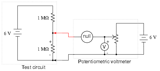
The circle symbol with the word "null"
written inside represents the null detector. This can be any
arbitrarily sensitive meter movement or voltage indicator.
Its sole purpose in this circuit is to indicate when there
is zero voltage: when the adjustable voltage source
(potentiometer) is precisely equal to the voltage drop in
the circuit under test. The more sensitive this null
detector is, the more precisely the adjustable source may be
adjusted to equal the voltage under test, and the more
precisely that test voltage may be measured.
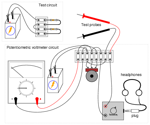
Build this circuit as shown in the
illustration and test its operation measuring the voltage
drop across one of the high-value resistors in the test
circuit. It may be easier to use a regular multimeter as a
null detector at first, until you become familiar with the
process of adjusting the potentiometer for a "null"
indication, then reading the voltmeter connected across the
potentiometer.
If you are using the headphone-based voltage
detector as your null meter, you will need to intermittently
make and break contact with the circuit under test and
listen for "clicking" sounds. Do this by firmly securing one
of the test probes to the test circuit and momentarily
touching the other test probe to the other point in the test
circuit again and again, listening for sounds in the
headphones indicating a difference of voltage between the
test circuit and the potentiometer. Adjust the potentiometer
until no clicking sounds can be heard from the headphones.
This indicates a "null" or "balanced" condition, and you may
read the voltmeter indication to see how much voltage is
dropped across the test circuit resistor. Unfortunately, the
headphone-based null detector provides no indication of
whether the potentiometer voltage is greater than, or
less than the test circuit voltage, so you will have
to listen for decreasing "click" intensity while
turning the potentiometer to determine if you need to adjust
the voltage higher or lower.
You may find that a single-turn ("3/4 turn")
potentiometer is too coarse of an adjustment device to
accurately "null" the measurement circuit. A multi-turn
potentiometer may be used instead of the single-turn unit
for greater adjustment precision, or the "precision
potentiometer" circuit described in an earlier experiment
may be used.
Prior to the advent of amplified voltmeter
technology, the potentiometric method was the only
method for making highly accurate voltage measurements. Even
now, electrical standards laboratories make use of this
technique along with the latest meter technology to minimize
meter "impact" errors and maximize measurement accuracy.
Although the potentiometric method requires more skill to
use than simply connecting a modern digital voltmeter across
a component, and is considered obsolete for all but the most
precise measurement applications, it is still a valuable
learning process for the new student of electronics, and a
useful technique for the hobbyist who may lack expensive
instrumentation in their home laboratory.
COMPUTER SIMULATION
Schematic with SPICE node numbers:
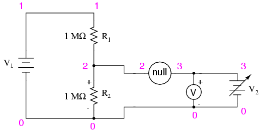
Netlist (make a text file containing the
following text, verbatim):
Potentiometric voltmeter
v1 1 0 dc 6
v2 3 0
r1 1 2 1meg
r2 2 0 1meg
rnull 2 3 10k
rmeter 3 0 50k
.dc v2 0 6 0.5
.print dc v(2,0) v(2,3) v(3,0)
.end
This SPICE simulation shows the actual
voltage across R2 of the test circuit, the null
detector's voltage, and the voltage across the adjustable
voltage source, as that source is adjusted from 0 volts to 6
volts in 0.5 volt steps. In the output of this simulation,
you will notice that the voltage across R2 is
impacted significantly when the measurement circuit is
unbalanced, returning to its true voltage only when there is
practically zero voltage across the null detector. At that
point, of course, the adjustable voltage source is at a
value of 3.000 volts: precisely equal to the (unaffected)
test circuit voltage drop.
What is the lesson to be learned from this
simulation? That a potentiometric voltmeter avoids impacting
the test circuit only when it is in a condition of
perfect balance ("null") with the test circuit!
|
